Tools for Practical Electronics, Chapter - II - Welcome back to our Practical Electronics Series! In the first chapter, we laid the groundwork by exploring the basics concepts of electronics and introduction to components like resistors and capacitors. Now, it’s time to roll up our sleeves and dive into the tools that will bring your projects to life. Whether you’re a newbie, a hobbyist, a student, or a seasoned pro, mastering the breadboard, multimeter, and soldering setup is your next step toward building and understanding circuits with confidence. My goal is to make this both accessible and practical, with clear explanations, step-by-step guidance, and tips I’ve picked up along the way. Let’s get started!
Tools for Practical Electronics: The Breadboard
What is a Breadboard and Why is it Useful?
A breadboard is your sandbox for electronics—a solderless prototyping tool that lets you build and test circuits in minutes. It’s a beginner’s best friend because it’s reusable and forgiving: no permanent commitments, no melted components. I’ve lost count of how many times a breadboard saved me from a design mistake before I committed it to solder.

How Does a Breadboard Work?
A standard solderless breadboard is a plastic block with a grid of holes, spaced 0.1 inches apart to match the pin spacing of most electronic components. Underneath, metal clips connect certain holes together:
- Rows (Horizontal): Each row in the main grid (often split by a central groove) is a single electrical node. Insert two component legs into the same row, and they’re connected.
- Power Rails (Vertical): On the sides, you’ll find two columns, typically marked with red and blue lines. These run vertically and are perfect for distributing power (like +5V) and ground across your circuit.

Using a Breadboard: Step-by-Step

A group of holes, as shown in the figure above, are interconnected, meaning the first and last holes in the row are electrically connected (shorted). When building a circuit on a breadboard, it is important to place only one leg of each component (such as an LED, resistor, or capacitor) in a single interconnected row. Placing both legs in the same row will create a short circuit, which may prevent the component from functioning properly or even cause damage. Proper component is shown below.

- Insert Components: Push the legs of components (e.g., resistors, LEDs, ICs) into the holes. The clips underneath grip them securely.
- Make Connections: Use jumper wires to link rows or connect to the power rails. For example, to light an LED, place its anode in one row with a resistor, and its cathode in another row tied to ground.
- Power Up: Attach a battery or power supply to the rails, then use wires to bring power to your circuit, as shown in figure below.

Tips for Success
- Stay Organized: Use color-coded wires—red for power, black for ground—to avoid confusion.
- Push Firmly: Components need to be fully seated for reliable connections.
- Plan Ahead: Sketch your circuit first to keep the layout clean and avoid spaghetti wiring.
Common Mistakes to Avoid
- Mixing up power rail directions (they run vertically, not across).
- Placing components in the same row when they shouldn’t connect.
- Forgetting to tie the power rails to your circuit—those rails don’t magically power everything!
Tools for Practical Electronics: The Multimeter
What is a Multimeter and Why is it Important?
A multimeter is your window into a circuit’s soul. It measures voltage, current, resistance, and more, making it indispensable for troubleshooting and verifying your work. I’ve chased down countless shorts and dead components with mine—it’s like having x-ray vision for electronics.
Types of Multimeters
You’ll find analog and digital multimeters, but digital multimeters (DMMs) are the way to go for most folks. They’re easier to read and more precise, which is a lifesaver when you’re just starting out.

Key Functions and How to Use Them
- Voltage (DC/AC): Set the dial to “V” (straight line for DC, wavy for AC). Touch the red probe to the positive point and the black to the negative or ground.
- Current (DC/AC): Switch to “A” and insert the multimeter in series with the circuit—break the path and let current flow through the meter.
- Resistance: Dial to “Ω” and touch the probes to each end of a component (circuit off, please!).
- Continuity: Look for the diode or sound wave symbol. It beeps when there’s a complete path—great for finding breaks or shorts.
Safety First
- Power Off for Resistance: Measuring resistance in a live circuit can fry your meter—or worse.
- Mind the Range: Start high and dial down to avoid overloads, especially with unknown voltages.
- Check Your Probes: Frayed leads are a safety hazard.
Practical Examples
- Battery Check: Set to DC voltage, probe the terminals, and see if it’s still got juice.

- Resistor Test: Use the Ω setting to confirm a resistor’s value matches its color code.

- Wire Hunt: Continuity mode will tell you if that mystery cable is intact.

Tips for Accurate Measurements
- Steady Hands: Wobbly probes give jumpy readings.
- Right Range: Too low, and you risk damage; too high, and precision suffers.
- Zero It Out: Some meters need a quick calibration tweak for spot-on results.
Maintenance and Care
- Swap out the battery when it’s low—dim displays are a giveaway.
- Keep it dry and dust-free to protect the internals.
Tools for Practical Electronics: The Soldering Setup
What is Soldering and Why is it Necessary?
Soldering creates permanent, reliable connections by melting a metal alloy (solder) to join components or wires. While breadboards are great for testing, soldering makes your projects robust and real. My first soldered circuit—a blinking LED board—still works years later, thanks to solid joints.

Components of a Basic Soldering Setup
- Soldering Iron: A 25-40W iron with a fine tip is perfect for electronics.
- Solder: Rosin-core, tin-lead (60/40) or lead-free works best.
- Stand and Sponge: Keeps your iron safe and its tip clean.
- Extras: Helping hands, a fume extractor, and safety glasses round out the kit.
Basic Soldering Techniques
- Heat the Iron: Set it to around 350°C (check your solder’s specs).
- Tin the Tip: Melt a thin layer of solder on the tip for better heat flow.
- Heat the Joint: Touch the iron to both the component lead and PCB pad for 2-3 seconds.
- Add Solder: Feed it in until it flows smoothly, forming a shiny cone.
- Cool Down: Pull the solder away first, then the iron, and let it solidify undisturbed.
Common Mistakes and How to Avoid Them
- Cold Joints: Dull, lumpy connections mean not enough heat—reheat and retry.
- Overheating: Too long on a joint can cook components; keep it under 5 seconds.
- Solder Blobs: Less is more—aim for neat, not excessive.
Desoldering Techniques
- Pump: Heat the joint and suck up the molten solder.
- Wick: Lay braided copper over the joint, heat it, and watch it soak up solder like a sponge.
Safety Precautions
- Ventilation: Solder fumes aren’t your lungs’ friends—crack a window or use a fume extractor.
- Burn Protection: That iron’s tip is 350°C—respect it!
- Eyes On: Safety glasses guard against stray solder splashes.
Maintenance of Soldering Equipment
- Wipe the tip with a damp sponge or use brass wool after each use.
- Tin the tip before storing to fend off oxidation.
- Replace tips when they wear out—don’t struggle with a dull one.
Tools for Practical Electronics: Power Supplies
A power supply is essential for providing the necessary voltage and current to your circuits. In electronics labs, bench power supplies are commonly used, offering adjustable voltage and current limits to suit various projects.
- Types of Power Supplies
- Linear power supplies: Simpler and provide clean, stable power with minimal noise but are less efficient and can be bulky.
- Switching power supplies: More efficient and compact but can introduce electrical noise, which may affect sensitive circuits.
For most hobbyist projects, a linear power supply is adequate. However, if space and efficiency are priorities, a switching supply can be used with proper filtering.
- Key Features
- Adjustable voltage and current limits: Allow you to set the desired output and protect your circuit from overcurrent conditions.
- Constant voltage (CV) and constant current (CC) modes: Useful for powering different types of loads and testing components like LEDs and batteries.
- Using a Power Supply Safely
- Always set the voltage and current limits before connecting to your circuit.
- Start with the voltage at zero and gradually increase it to the desired level.
- Monitor the current to ensure it doesn’t exceed your circuit’s requirements. If the current limit is reached, the power supply will switch to CC mode, reducing the voltage to protect the circuit.
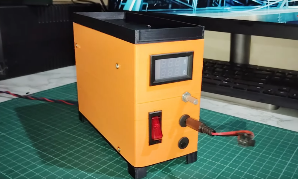
The above shown variable power supply is made by me. You you want to learn more about that you can visit – DIY Variable Power Supply made using 3D Printing for Lab Bench
Tools for Practical Electronics: Alternative Power Supply Options
While bench power supplies are ideal for lab settings, hobbyists and students may need more portable or cost-effective alternatives for powering their projects. This section explores additional options and their practical applications.
- Battery-Based Power Supplies
Batteries are a simple and portable solution for low-power circuits. Common options include:- 9V batteries: Widely used for small projects like Arduino-based designs.
- AA or AAA batteries: Often combined in series or parallel to achieve the desired voltage and capacity.
- Lithium-ion batteries: Rechargeable and suitable for higher-power applications, though they require proper charging circuits for safety.
When using batteries, always include a switch to control power and monitor voltage levels to avoid damaging components as the battery drains.
- Wall Adapters (AC-to-DC Converters)
Wall adapters, or “wall warts,” convert household AC power to a fixed DC voltage (e.g., 5V, 12V). They’re affordable and convenient for projects requiring stable power without frequent adjustments.- Choosing the Right Adapter: Check the voltage, current rating, and connector polarity (usually indicated on the adapter) to match your circuit’s needs.
- Limitations: Unlike bench supplies, most wall adapters offer fixed outputs and lack current limiting, so add a fuse or regulator if needed.
- Practical Applications
- Prototyping: Use a bench supply for flexibility during testing, then switch to a battery or adapter for a final portable design.
- Field Work: Batteries excel in mobile projects, like robotics, where a bench supply isn’t practical.
- Cost Savings: Wall adapters are an economical choice for fixed-voltage projects, such as powering LED strips or simple sensors.
- Safety Note
When using alternative power supplies, ensure proper insulation and avoid overloading. For batteries, use holders or connectors to prevent short circuits, and for wall adapters, verify the output matches your circuit’s requirements before connecting.
Tools for Practical Electronics: Other Tools
These are the fundamental tools used for assembling, disassembling, and handling electronic components.
🔧 Screwdrivers and Nut Drivers
- Purpose: For tightening and loosening screws on enclosures, circuit boards, or panels.
- Types:
- Flat-head and Phillips-head screwdrivers.
- Precision screwdriver set (for small electronic devices).
- Nut drivers (for tightening nuts on switches, connectors, and terminals).
✂️ Pliers and Cutters
- Long-nose pliers: For bending and gripping wires, especially in tight spaces.
- Diagonal cutters: For cutting wires and component leads.
- Wire strippers: For removing insulation from wires without damaging the core.
- Tweezers: For handling small components like surface-mount devices (SMDs).
📊 Oscilloscope
- Purpose: For visualizing electrical signals and waveforms.
- Usage: Essential for debugging and analyzing signal characteristics in analog and digital circuits.
🔧 Signal Generator
- Purpose: Generates various waveforms (sine, square, triangle) for testing circuits.
- Applications: Used in testing filters, amplifiers, and other analog circuits.
🧰 Perfboard and PCB
- Perfboard: For semi-permanent prototyping. Components are soldered onto the board.
- PCB (Printed Circuit Board): For finalizing and manufacturing your circuit design.
Conclusion
There you have it—the breadboard, multimeter, and soldering setup, your gateway to practical electronics. These tools aren’t just gear; they’re skills that grow with you. Start simple: wire up an LED on a breadboard, measure its voltage drop, then solder it onto a scrap PCB. Mistakes are part of the journey—I’ve melted my share of components learning these ropes.
Next time, we’ll use these tools to build a proper project: a tricked-out LED circuit that does more than just blink. Until then, grab your gear, experiment, and have fun. Happy tinkering!
In the Next section, we will learn about the essential tools required for practical electronics –
Pingback: Practical Electronics for Beginners and Non Electronics Guys - TechKnowLab