Temperature measurement is a critical parameter in almost every engineering system—whether it’s 3D printing, industrial automation, HVAC, heat treatment, or laboratory research. While common sensors like thermistors and thermocouples are easy to use, they often fall short when accuracy, stability, and repeatability are required. RTD PT-100 temperature sensors are widely used when high accuracy and stable readings are required.
In this article, you’ll learn how to interface a 3-wire PT-100 RTD temperature sensor with the MAX31865 RTD-to-Digital Converter Module using Arduino.
We’ll cover working principle, wiring, circuit, Arduino code, calibration tips, and real-world applications—all explained step by step.
What is RTD Sensor?
Resistance Temperature Detectors (RTDs) are sensors in which the electrical resistance changes with temperature. Platinum is the most commonly used and most accurate material, and RTDs made with platinum are called PT-RTDs. Other metals such as nickel and copper can also be used to make RTDs. Platinum RTDs have a wide operating temperature range (up to more than +800 °C), high accuracy, good repeatability, and fairly linear response.
PT-RTDs
For PT-RTDs, the most common nominal resistance values at 0 °C are 100 Ω and 1000 Ω, although other values are also available. The average rate at which resistance changes with temperature between 0 °C and +100 °C is called alpha (α). This value depends on the purity of the platinum and the amount of impurities present. The two most commonly used alpha values are 0.00385 and 0.00392, which correspond to the IEC 751 (PT100) standard and the SAMA standard, respectively.
Callendar-Van Dusen equation
The relationship between resistance and temperature in an RTD is mostly linear, but it has a small amount of curvature. This behavior is described by the Callendar–Van Dusen equation, which accurately represents how RTD resistance changes with temperature:
R(T) = R₀ (1 + aT + bT² + c(T − 100)T³)
Where:
- T is the temperature in °C
- R(T) is the resistance at temperature T
- R₀ is the resistance at 0 °C
According to the IEC 751 standard, the value of α (alpha) is 0.00385055, and the Callendar–Van Dusen coefficients are:
- a = 3.90830 × 10⁻³
- b = −5.77500 × 10⁻⁷
- c = −4.18301 × 10⁻¹² for temperatures from −200 °C to 0 °C
- c = 0 for temperatures from 0 °C to +850 °C
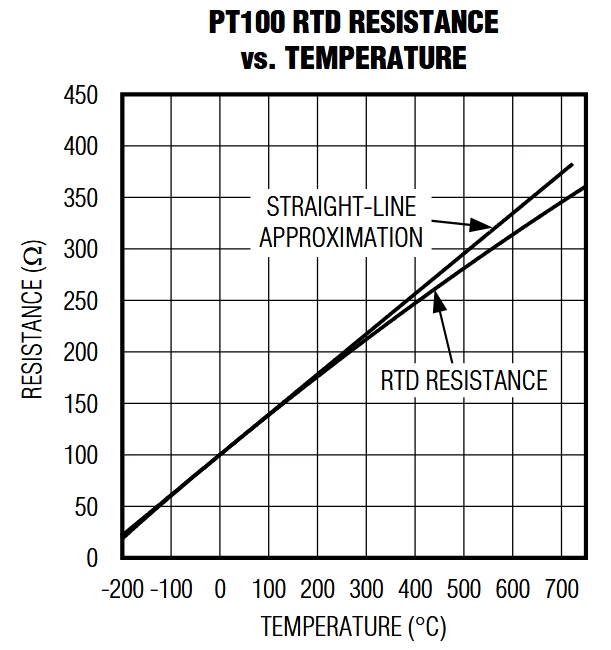
The resistance-versus-temperature curve for a PT100 RTD closely follows this equation. A straight-line approximation is often used for simplicity, based on the slope between 0 °C and +100 °C, but the Callendar–Van Dusen equation provides more accurate results over a wide temperature range.
To obtain accurate temperature readings, especially at higher temperatures, this equation must be used to account for the non-linear behavior of the RTD. However, when using the Adafruit_MAX31865 library, this calculation is already implemented internally. Because of this, the user does not need to manually apply the Callendar–Van Dusen equation, and the temperature values provided by the library are already compensated and accurate.
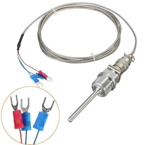
What is RTD PT-100 Temperature Sensor?
An RTD (Resistance Temperature Detector) is a sensor whose electrical resistance changes predictably with temperature.
Platinum RTDs are preferred because platinum offers:
- Excellent linearity
- Long-term stability
- High accuracy over a wide temperature range
Why It’s Called PT-100
This temperature is called as “PT-100” due to its material and its temperature-resistance relationship characteristics shown below:
- PT → Platinum element
- 100 → Resistance is 100 Ω at 0°C
As temperature increases, the resistance increases in a nearly linear manner.
PT-100 Key Characteristics
| Characteristics | Value |
|---|---|
| Resistance @ 0°C | 100 Ω |
| Temperature Range | −200°C to +850°C |
| Accuracy | Very High |
| Drift | Extremely Low |
| Industrial Acceptance | Global Standard |
Types of Wiring Configurations in RTDs
RTD sensors are available in different wiring configurations. The number of wires mainly affects measurement accuracy by handling the resistance of connecting wires. RTDs come in 2-wire, 3-wire, or 4-wire configurations, with the 3-wire configuration being the most common one.
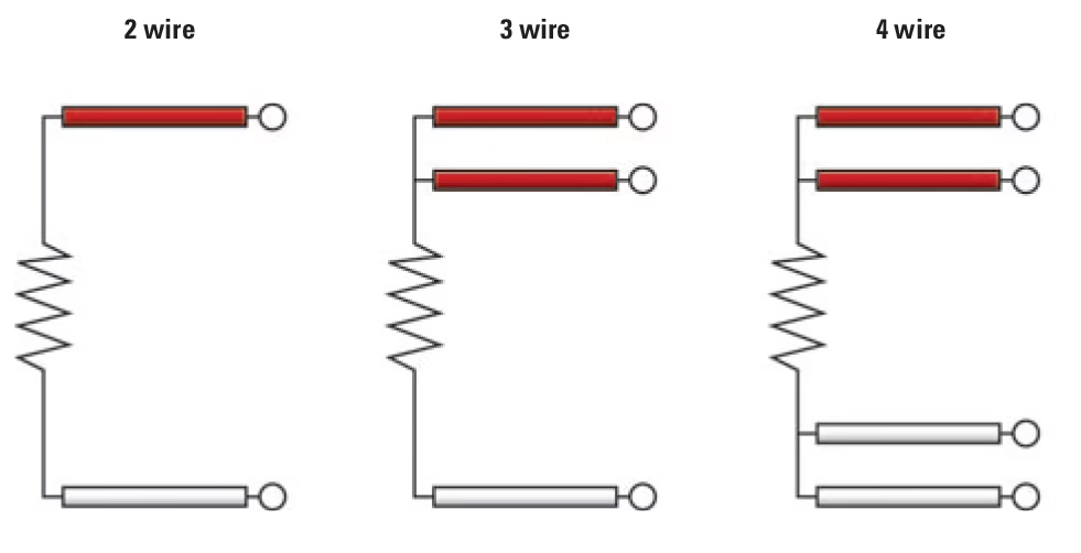
2 Wire RTDs
In a 2-wire RTD, the same two wires are used to supply current and measure resistance. The resistance of the lead wires adds to the sensor resistance, which causes measurement error. This configuration is simple and low cost, but accuracy is limited. It is suitable only for short cable lengths and low-precision applications.
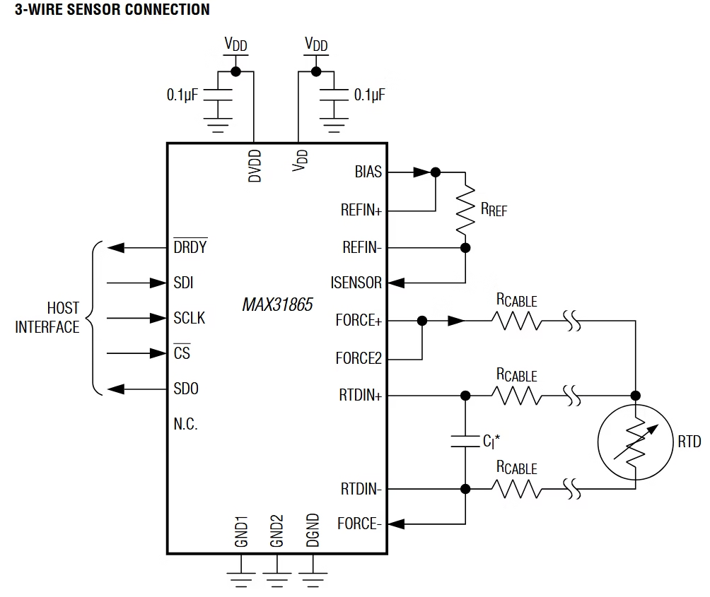
3-Wire RTD
A 3-wire RTD uses an additional wire to reduce the effect of lead wire resistance. The measuring circuit assumes that the two lead wires have equal resistance and compensates for most of the error. This configuration offers much better accuracy than a 2-wire RTD and is widely used in industrial applications.
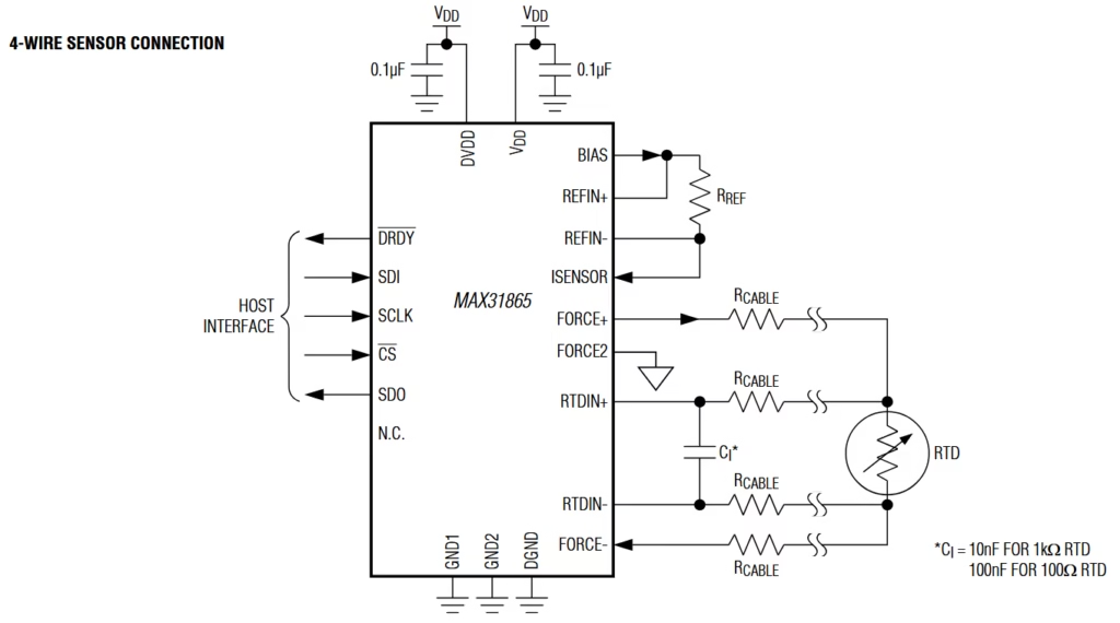
4-Wire RTD
A 4-wire RTD completely eliminates the effect of lead wire resistance by using separate wires for current supply and voltage measurement. This provides the highest accuracy among all configurations and is the most complex. Because of its higher cost and complexity, it is mainly used in laboratories and high-precision measurement systems.
Why Choose a 3-Wire PT-100 Configuration?
RTD sensors are available in 2-wire, 3-wire, and 4-wire configurations.
The Problem with Lead Resistance
RTDs measure resistance. Long connecting wires also have resistance. This extra resistance causes error in temperature reading.
Long wires add extra resistance → measurement error.
Therefore 2 Wire has low accuracy and 4 wire has very high accuracy but costs more.
Solution: 3-Wire RTD
A 3-wire configuration compensates for lead wire resistance electronically, making it the most widely used industrial standard.
Comparison Table
| RTD Type | Accuracy | Cost | Usage |
|---|---|---|---|
| 2-Wire | Low | Low | Short cables |
| 3-Wire | High | Medium | Industrial & research |
| 4-Wire | Very High | High | Metrology labs |
For Arduino-based projects, 3-wire PT-100 is the best balance. In this tutorial also, I am using a 3-Wire RTD temperature sensor.
Testing a PT100 RTD Using a Multimeter
RTDs have very low resistance, and the resistance of long connecting wires (often 1–4 Ω) can cause noticeable temperature errors. Even a small wire resistance can result in an error of 0.5 °C or more, which is not acceptable for precise temperature measurement.
For 2-wire, 3-wire, and 4-wire RTD configurations: You can check whether a PT100 RTD is working correctly using a digital multimeter set to resistance (Ω) mode. The test is simple and helps confirm that the sensor is not broken or shorted. Images shown below in this section are taken from adafruit.com
Testing a 2-Wire PT100 RTD
- Set the multimeter to resistance (Ω) mode.
- Connect the multimeter probes to the two RTD wires (102Ω).
- If you then place the sensor into an ice bath (0°C) the resistance should drop to 100Ω (For example, at 0 °C, even if the total measured resistance is 102 Ω due to wire resistance, the measurement system subtracts the wire resistance and correctly calculates 100 Ω for the RTD).
- At room temperature (around 25 °C), the resistance should be close to 109–110 Ω.
Result check:
- Near 0 Ω → Short circuit (faulty sensor)
- Resistance near 100 Ω at 0 °C → Sensor is OK
- Very high or infinite resistance → Open circuit (faulty sensor)
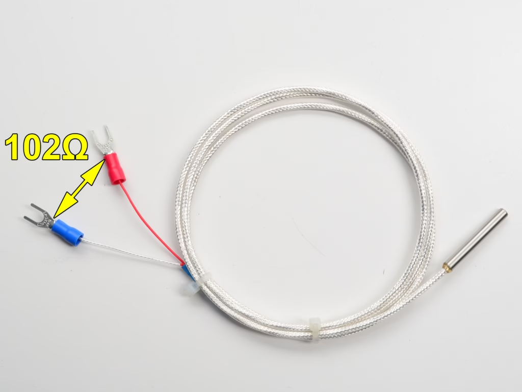
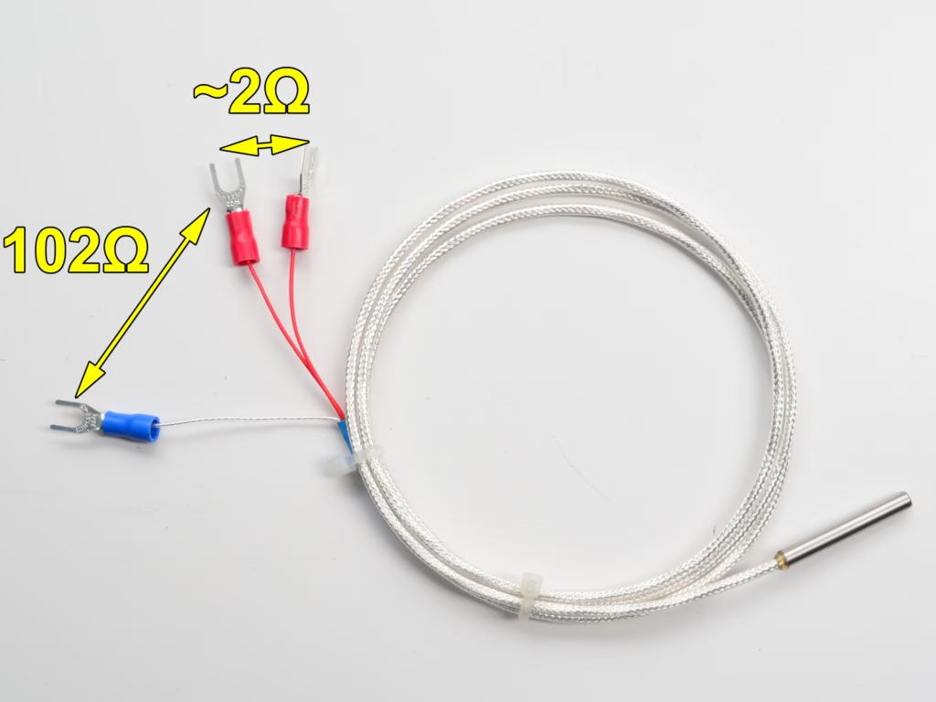
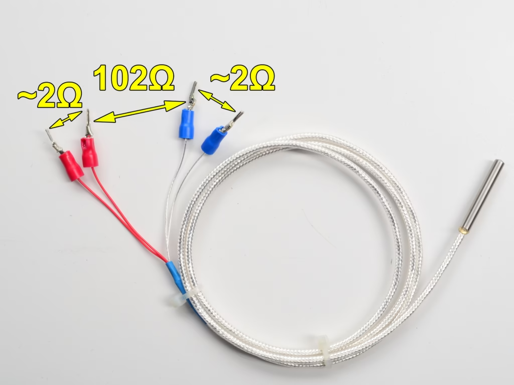
Testing a 3-Wire PT100 RTD
- Identify the two same-color wires and the one different-color wire.
- Measure resistance between the two same-color wires → reading should be very low (lead resistance only – 2 Ω ).
- Measure resistance between each same-color wire and the different-color wire.
- Both readings should be nearly equal and close to the expected PT100 value (about 109–110 Ω at room temperature).
Result check:
- Large difference between readings → Possible wire or sensor damage
- Equal readings → Sensor is working correctly
Testing a 4-Wire PT100 RTD
- Measure resistance between the two current wires.
- Measure resistance between the two voltage-sense wires.
- Both measurements should give almost the same resistance value, close to the PT100 resistance at the current temperature.
Result check:
- Very low resistance → Short circuit
- Similar resistance values → Sensor is OK
- No reading or very high resistance → Open circuit
Quick Tip 💡
- If possible, place the sensor tip in ice water (0 °C). The resistance should be very close to 100 Ω, which confirms correct operation.
This simple multimeter test works for all RTD wiring configurations and is useful before connecting the PT100 to a measurement circuit or module.
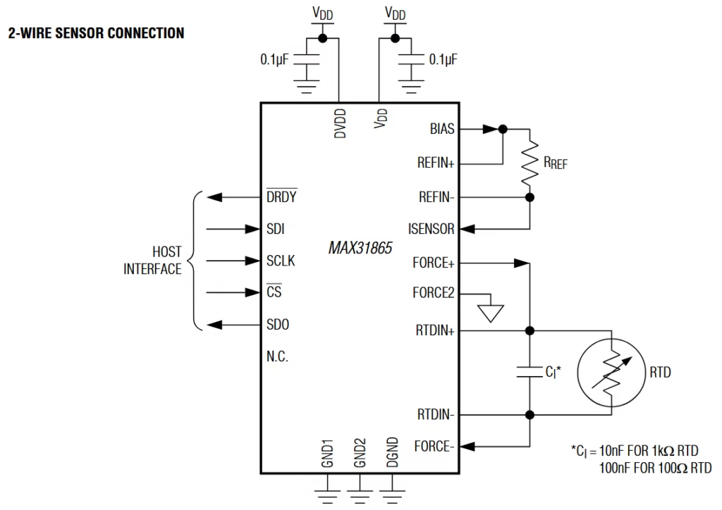
What is the MAX31865 Module?
The MAX31865 is a special IC that converts RTD resistance into digital temperature data. Instead of manually measuring resistance measuring resistance using ADCs (which is noisy and inaccurate), this module does everything internally and sends accurate data to Arduino using SPI communication. We can also say that the MAX31865 is a precision RTD-to-Digital Converter IC specifically designed for PT-100 and PT-1000 sensors.
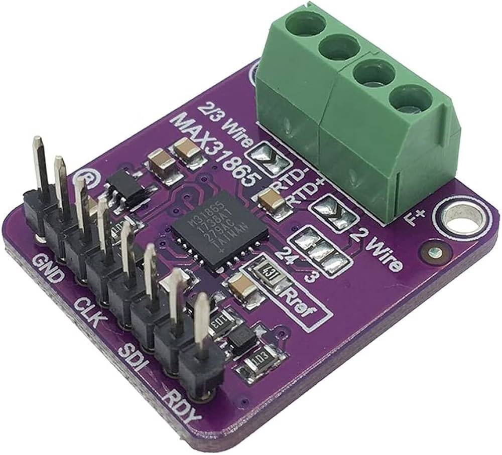
Key Features of MAX31865
- Supports PT-100 and PT-1000
- 2-wire, 3-wire, and 4-wire RTDs
- High-resolution 15-bit ADC
- Built-in fault detection for broken sensors
- SPI interface (noise-resistant)
- Ideal for industrial environments
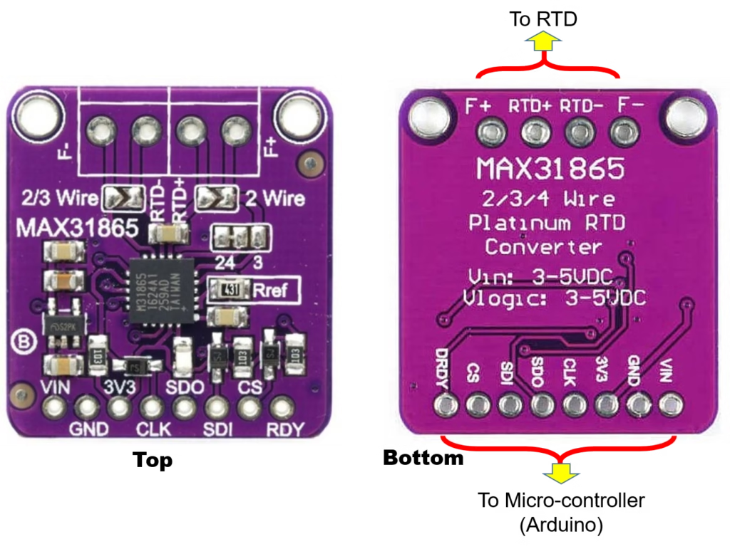
MAX31865 Pin Description
| Pin | Description |
|---|---|
| VIN | 3.3V / 5V supply |
| GND | Ground |
| SCK | SPI Clock |
| SDI | SPI MOSI |
| SDO | SPI MISO |
| CS | Chip Select |
| RTD+ / RTD- | PT-100 connection |
The detailed technical description of the MAX31865 module can be seen in its data sheet.
Set jumper on MAX31865 board to 3-wire mode
Before connecting the PT100 sensor, the MAX31865 breakout board must be configured for 3-wire RTD Mode.
Steps to configure the board:
- Solder the pads labeled “2/3 Wire” together.
- In the section labeled “2/4 3”, solder the two right-most pads together.
- Cut the thin trace between the two left-most pads in the same “2/4 3” section.
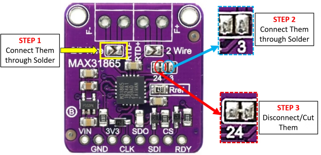
Important notes:
- The trace to be cut is very thin and may be hard to see.
- Use a sharp knife or blade and avoid cutting nearby traces.
- After cutting, use a multimeter in continuity mode to confirm there is no electrical connection between the left and right pads.
Once these steps are completed, the MAX31865 board is correctly set for 3-wire PT100 RTD operation.
Circuit Connection: PT-100 + MAX31865 + Arduino
Connecting the 3-Wire PT-100
- Two identical-color wires → RTD+
- Single different-color wire → RTD-
- Set jumper on MAX31865 board to 3-wire mode
⚠️ Wrong jumper setting is the #1 cause of incorrect readings.
How to Connect PT-100 (3-Wire) with MAX31865 and Arduino
I am explaining Step-by-Step Circuit Connection below:
Things Required
- PT-100 3-wire temperature sensor
- MAX31865 RTD module
- Arduino UNO (or compatible)
- Jumper wires
- USB cable
Step 1: Power Off the Arduino
Before making any connections:
- Disconnect the USB cable from Arduino
- Make sure no power is supplied
This helps avoid damage to the module and Arduino.
Step 2: Identify MAX31865 Pins
On the MAX31865 module, locate these pins:
- VIN
- GND
- SCK
- SDI
- SDO
- CS
- RTD+
- RTD-
Check the labels printed on the PCB, as shown in a figure above.
Step 3: Connect Power Supply
- Connect VIN of MAX31865 to 5V pin of Arduino
- Connect GND of MAX31865 to GND pin of Arduino
This supplies power to the MAX31865 module (but keep the power supply off for now).
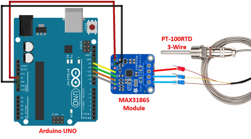
Step 4: Connect SPI Communication Pins
Now connect the SPI pins between Arduino UNO and MAX31865.
- Connect SCK of MAX31865 to D13 of Arduino
- Connect SDI of MAX31865 to D11 of Arduino
- Connect SDO of MAX31865 to D12 of Arduino
- Connect CS of MAX31865 to D10 of Arduino
These connections allow Arduino to read temperature data from the module.
Step 5: Set the MAX31865 Module to 3-Wire Mode
- This step has already been explained above with complete detail, Follow it carefully. On the MAX31865 board, locate the wire-selection jumper Set the jumper to 3-wire configuration.
💡 This step is very important. Wrong jumper setting will give incorrect temperature readings.
Step 6: Identify PT-100 Sensor Wires
A 3-wire PT-100 sensor usually has:
- Two wires of the same color
- One wire of a different color
Example:
- Two red wires → same color
- One white wire → different color
Step 7: Connect PT-100 to MAX31865
- Connect the two same-color wires of PT-100 to RTD+ terminals
- Connect the single different-color wire to RTD- terminal
Tighten the screw terminals properly to avoid loose contact.
Step 8: Recheck All Connections
Before powering ON:
- Check power connections
- Check SPI pin connections
- Confirm jumper is set to 3-wire mode
- Confirm PT-100 wires are firmly connected
Step 9: Power the Arduino
- Connect USB cable to Arduino
- Open Arduino IDE
- Upload the MAX31865 Arduino code (as given below)
After uploading:
- Open Serial Monitor
- Set baud rate to 9600
- Temperature value should appear in °C
Step 10: Verify Sensor Operation
- Touch the PT-100 probe with your hand
- Temperature value should slowly increase
- This confirms the circuit is working correctly
Summary of Connections for Arduino UNO to MAX31865 (SPI)
| MAX31865 Pin | Arduino UNO Pin |
|---|---|
| VIN | 5V |
| GND | GND |
| SCK | D13 |
| SDI | D11 |
| SDO | D12 |
| CS | D10 |
| RTD+ | Two same-color PT-100 wires |
| RTD- | Single different-color PT-100 wire |
How the System Works
- MAX31865 injects a constant current into the PT-100
- PT-100 resistance changes with temperature
- MAX31865 measures resistance precisely
- Resistance is converted to temperature internally
- Arduino reads temperature digitally via SPI
This method eliminates ADC noise, wire resistance errors, and calibration complexity.
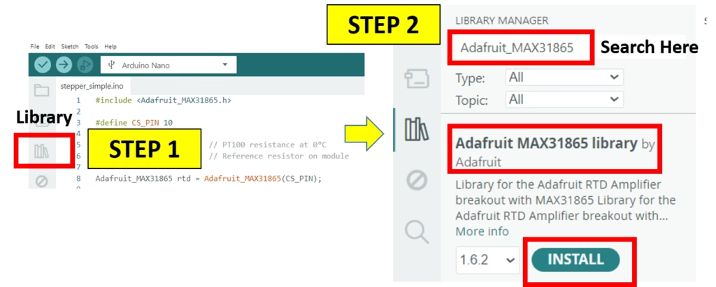
Arduino Code for PT-100 + MAX31865
Download Adafruit_MAX31865 library
Before proceeding to the Arduino code for PT-100 RTD and MAX31865, we must have the library of MAX31865 module. Therefore, the process steps for downloading the MAX31865 library in Arduino IDE is given in the image below. Follow these steps and install the library first.
#include <Adafruit_MAX31865.h>

// Use software SPI: CS, DI, DO, CLK
Adafruit_MAX31865 thermo = Adafruit_MAX31865(10, 11, 12, 13);
// use hardware SPI, just pass in the CS pin
//Adafruit_MAX31865 thermo = Adafruit_MAX31865(10);

// The value of the Rref resistor. Use 430.0 for PT100 and 4300.0 for PT1000
#define RREF      430.0
// The 'nominal' 0-degrees-C resistance of the sensor
// 100.0 for PT100, 1000.0 for PT1000
#define RNOMINAL  100.0

void setup() {
  Serial.begin(9600);
  Serial.println("Adafruit MAX31865 PT100 Sensor Test!");

  thermo.begin(MAX31865_3WIRE);  // set to 2WIRE or 4WIRE as necessary
}


void loop() {
  uint16_t rtd = thermo.readRTD();

  Serial.print("RTD value: "); Serial.println(rtd);
  float ratio = rtd;
  ratio /= 32768;
  Serial.print("Ratio = "); Serial.println(ratio,8);
  Serial.print("Resistance = "); Serial.println(RREF*ratio,8);
  Serial.print("Temperature = "); Serial.println(thermo.temperature(RNOMINAL, RREF));

  // Check and print any faults
  uint8_t fault = thermo.readFault();
  if (fault) {
    Serial.print("Fault 0x"); Serial.println(fault, HEX);
    if (fault & MAX31865_FAULT_HIGHTHRESH) {
      Serial.println("RTD High Threshold");
    }
    if (fault & MAX31865_FAULT_LOWTHRESH) {
      Serial.println("RTD Low Threshold");
    }
    if (fault & MAX31865_FAULT_REFINLOW) {
      Serial.println("REFIN- > 0.85 x Bias");
    }
    if (fault & MAX31865_FAULT_REFINHIGH) {
      Serial.println("REFIN- < 0.85 x Bias - FORCE- open");
    }
    if (fault & MAX31865_FAULT_RTDINLOW) {
      Serial.println("RTDIN- < 0.85 x Bias - FORCE- open");
    }
    if (fault & MAX31865_FAULT_OVUV) {
      Serial.println("Under/Over voltage");
    }
    thermo.clearFault();
  }
  Serial.println();
  delay(1000);
}
Calibration Tips for Maximum Accuracy
- Use shielded twisted-pair cables
- Keep RTD wires away from heaters & motors
- Verify RREF resistor value on your module
- Perform ice-bath calibration (0°C)
- Average multiple readings in software
💡 With proper setup, accuracy better than ±0.3°C is achievable.
Where This Setup Is Used (Real-World Applications)
- Industrial process monitoring
- 3D printer hot-end & heated chamber sensing
- Furnaces and heat treatment
- HVAC systems
- Research laboratories
- Food & pharmaceutical industries
PT-100 vs Thermocouple vs Thermistor
| Sensor | Accuracy | Stability | Best Use |
|---|---|---|---|
| PT-100 RTD | ⭐⭐⭐⭐⭐ | Excellent | Industrial & research |
| Thermocouple | ⭐⭐⭐ | Medium | Very high temperatures |
| Thermistor | ⭐⭐⭐⭐ | Low | Consumer electronics |
👉 If precision and repeatability matter, PT-100 wins.
Conclusion
The combination of a 3-wire PT-100 RTD and MAX31865 module with Arduino delivers industrial-grade temperature measurement with digital simplicity.
It’s one of the best temperature sensing solutions for serious electronics, mechatronics, and research projects.
If you’re building professional systems—not just hobby demos—this setup is worth every rupee.
Frequently Asked Questions (FAQs)
What is a PT100 RTD temperature sensor?
A PT100 is a resistance temperature detector made from platinum. It has a resistance of 100 ohms at 0 °C and provides accurate and stable temperature measurements.
Why is PT100 more accurate than thermistors?
PT100 sensors have better stability, repeatability, and linearity over a wide temperature range, making them suitable for industrial and laboratory applications.
What is the difference between PT100 and PT1000?
The main difference is nominal resistance at 0 °C. PT100 has 100 Ω, while PT1000 has 1000 Ω. PT1000 is more suitable for long cable lengths due to lower error from wire resistance.
Why is a 3-wire PT100 commonly used?
A 3-wire PT100 reduces the effect of lead wire resistance and provides good accuracy at a reasonable cost. It is widely used in industrial systems.
What is the function of the MAX31865 module?
The MAX31865 converts the resistance of a PT100 or PT1000 sensor into digital temperature data and communicates with Arduino using SPI.
Can MAX31865 work with both PT100 and PT1000?
Yes, MAX31865 supports both PT100 and PT1000 sensors. The correct nominal resistance value must be set in the Arduino code.
Why do I need to set the jumper for 3-wire mode on MAX31865?
The jumper configuration tells the MAX31865 how the RTD is wired. Incorrect jumper settings will result in wrong temperature readings.
How can I test a PT100 sensor without Arduino?
You can test a PT100 using a digital multimeter in resistance mode. At 0 °C, it should read close to 100 Ω. At room temperature, it will be slightly higher.
What causes incorrect temperature readings?
Common causes include wrong wiring, incorrect jumper configuration, loose connections, electrical noise, or incorrect reference resistor values.
Is calibration required for PT100 sensors?
Basic calibration improves accuracy, especially for 2-wire RTDs. For 3-wire and 4-wire RTDs with MAX31865, calibration is usually minimal.
Can this setup measure high temperatures?
Yes, PT100 sensors can measure temperatures up to around 850 °C, but the actual limit depends on the probe type and insulation used.
Which Arduino boards are compatible with MAX31865?
MAX31865 works with Arduino UNO, Nano, Mega, and other boards that support SPI communication.