If you’re looking to build an affordable Arduino Spin Coating System for laboratory experiments or educational projects, this guide will help you create one using readily available components. The project uses an Arduino Nano, a Brushless DC (BLDC) motor, an Electronic Speed Controller (ESC), an IR speed sensor, and a 16×2 LCD to achieve adjustable rotational speed with real-time RPM monitoring.
Spin coating is one of the most widely used techniques for producing uniform thin films in MEMS fabrication, semiconductor processing, polymer research, biosensors, and nanotechnology. Commercial spin coaters are often expensive, but this DIY implementation provides a practical alternative for students, researchers, and makers.
What Is a Spin Coating System?
A spin coating system spreads a liquid material over a flat substrate by rotating it at high speed. Centrifugal force distributes the liquid evenly, producing a thin and uniform coating after solvent evaporation.
Typical applications include:
- MEMS fabrication
- Photoresist coating
- Polymer thin-film deposition
- Solar cell research
- Optical coatings
- Biosensors
- Nanomaterials research
- University laboratory experiments
Features of This Arduino Spin Coating System
- Adjustable spin speed using a potentiometer
- Real-time RPM display on a 16×2 LCD
- Arduino Nano-based controller
- ESC-driven BLDC motor
- Interrupt-based RPM measurement using an IR sensor
- Budget-friendly and easy to assemble
- Expandable for research applications
Components Required for Arduino Spin Coating System
| Component | Quantity |
|---|---|
| Arduino Nano | 1 |
| Brushless DC Motor | 1 |
| Electronic Speed Controller (ESC) | 1 |
| IR Speed Sensor Module | 1 |
| 16×2 LCD Display | 1 |
| 10k Potentiometer (Speed Control) | 1 |
| 10k Potentiometer (LCD Contrast) | 1 |
| 220 Ω Resistor | 1 |
| 7.5–12 V DC Power Supply | 1 |
| Breadboard and Jumper Wires | As required |
| Mounting Base and Spin Platform | 1 |
Working Principle of Arduino Spin Coating System
The Arduino continuously reads the speed control potentiometer connected to analog pin A0. The input is mapped to a PWM pulse width between 1000 µs and 2000 µs and sent to the ESC, which controls the BLDC motor speed.
An IR sensor detects every revolution of the rotating platform using a reflective marker. The Arduino counts these pulses through an interrupt and calculates the RPM, which is displayed on the LCD in real time.
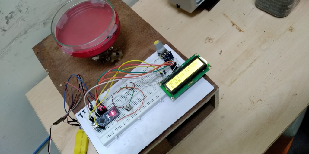
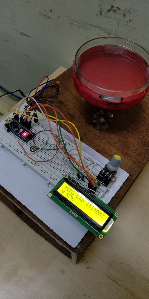
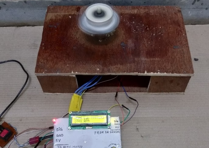
Hardware Overview
The assembled prototype consists of:
- A rotating spin platform mounted on the BLDC motor shaft
- Arduino Nano controller mounted on a breadboard
- ESC for motor control
- IR speed sensor for RPM feedback
- Speed adjustment potentiometer
- 16×2 LCD displaying measured RPM
- External DC power supply
The modular design makes future upgrades straightforward, including PID speed control, programmable spin profiles, Wi-Fi connectivity, and data logging.
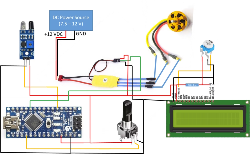
Circuit Diagram of Arduino Spin Coating System
The following wiring diagram illustrates the complete setup:
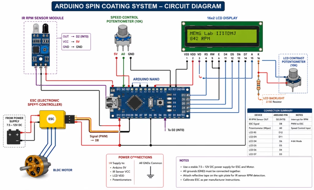
Pin Connections
Arduino Nano
| Arduino Pin | Connected To |
|---|---|
| A0 | Speed Control Potentiometer |
| D2 (INT0) | IR Speed Sensor OUT |
| D8 | ESC Signal Wire |
| D12 | LCD RS |
| D11 | LCD EN |
| D6 | LCD D4 |
| D5 | LCD D5 |
| D4 | LCD D6 |
| D3 | LCD D7 |
| 5V | LCD, Sensor, Potentiometers |
| GND | Common Ground |
ESC Connections
| ESC Wire | Connection |
|---|---|
| Signal | Arduino D8 |
| Power (+) | 7.5–12V DC Supply |
| Ground | Common Ground |
| Three Motor Wires | BLDC Motor |
IR Sensor
| Pin | Connection |
|---|---|
| VCC | 5V |
| GND | GND |
| OUT | D2 (Interrupt Pin) |
LCD Contrast
Connect the middle pin of a 10k potentiometer to the LCD contrast pin (VO), with the outer pins connected to 5V and GND.
Also Read: ST7735 TFT Display Arduino Tutorial | Create a Romantic Animated Message
Arduino Program for Arduino Spin Coating System
The Arduino sketch reads the potentiometer, generates ESC control pulses, counts IR sensor interrupts, calculates RPM, and updates the LCD display continuously.
Key operations include:
- Analog input reading from A0
- Mapping values to 1000–2000 µs ESC pulses
- Interrupt-based pulse counting
- RPM computation
- LCD display updates
- Serial monitoring for debugging
The following sketch controls the ESC and displays measured RPM:
#include <LiquidCrystal.h>
#include <Servo.h>

Servo esc;
LiquidCrystal lcd(12,11,6,5,4,3);

float value = 0;
float rev = 0;
int rpm;
int oldtime = 0;
int time;

void isr()
{
  rev++;
}

void setup()
{
  Serial.begin(9600);

  lcd.begin(16,2);

  attachInterrupt(0, isr, RISING);

  esc.attach(8);

  esc.writeMicroseconds(1000);
}

void loop()
{
  int val;

  val = analogRead(A0);

  val = map(val, 0, 1023, 1000, 2000);

  Serial.print("Pulse Width(ms): ");
  Serial.print(val);
  Serial.print("  ");

  esc.writeMicroseconds(val);

  delay(1000);

  detachInterrupt(0);

  time = millis() - oldtime;

  rpm = (rev / time) * 60000;

  oldtime = millis();

  rev = 0;

  lcd.clear();
  lcd.setCursor(0,0);
  lcd.print("MEMS Lab IIITDMJ");

  lcd.setCursor(0,1);
  lcd.print(rpm);
  lcd.print(" RPM");

  Serial.print("RPM: ");
  Serial.println(rpm);

  attachInterrupt(0, isr, RISING);
}
Code Explanation
ESC Control
val = analogRead(A0);
val = map(val, 0, 1023, 1000, 2000);
esc.writeMicroseconds(val);
The potentiometer reading is converted into an ESC-compatible PWM pulse width from 1000 µs (minimum throttle) to 2000 µs (maximum throttle).
RPM Measurement
attachInterrupt(0, isr, RISING);Every pulse from the IR sensor triggers the interrupt service routine:
void isr()
{
    rev++;
}
The RPM is calculated using:
rpm = (rev / time) * 60000;where time is measured in milliseconds.
How to Calibrate the ESC
- Disconnect the BLDC motor from the spin plate.
- Upload the sketch.
- Set the potentiometer to minimum.
- Power on the ESC.
- Wait for initialization beeps.
- Slowly increase the potentiometer to verify smooth speed changes.
- Mount the spin plate after confirming correct operation.
Also Read: How to Use PT-100 RTD with MAX31865 Module and Arduino
Advantages of Arduino Spin Coating System
- Significantly lower cost than commercial systems
- Easy to reproduce using common components
- Suitable for engineering education and research
- Real-time RPM monitoring improves repeatability
- Flexible and customizable architecture
Future Improvements
The system can be enhanced with:
- Closed-loop PID speed regulation
- Preset spin recipes
- Touchscreen interface
- SD card data logging
- Wireless monitoring
- Automatic acceleration and deceleration profiles
- Safety enclosure with lid interlock
Safety Precautions while using Arduino Spin Coating System
- Always secure the substrate before spinning.
- Ensure the rotating platform is properly balanced.
- Wear eye protection during operation.
- Use a protective enclosure when operating at high speeds.
- Keep loose objects and wiring away from rotating components.
- Verify that the power supply matches the ESC and motor specifications.
Conclusion
This DIY Arduino Spin Coating System demonstrates that an effective laboratory spin coater can be built using affordable off-the-shelf components. By combining an Arduino Nano, BLDC motor, ESC, IR sensor, and LCD display, the system provides adjustable speed control and reliable RPM feedback, making it an excellent platform for MEMS research, thin-film deposition, educational laboratories, and engineering projects.
Whether you are a student, researcher, or electronics enthusiast, this project offers an accessible way to explore spin coating technology while leaving ample room for future enhancements and customization.