The Smart Street Light System project, utilizing Arduino and a PIR sensor, improves energy efficiency by automating lighting through motion detection. Traditional setups often waste energy as lights stay on in empty spaces. This project tackles the problem by integrating a Passive Infrared (PIR) sensor, capable of detecting human motion, with an Arduino microcontroller for intelligent control.
Working of Smart Street Light
The Smart Lighting System operates using a motion sensor to detect human movement. When motion is detected, the Arduino activates the lights for illumination, and it automatically turns them off when no motion is sensed, ensuring energy-efficient lighting control.
Components Required
To complete this smart street light project using Arduino and PIR sensor, we will be needing following components (The components listed below may contain some affiliate links, if you purchase the components from these links, It will be like buying a coffee for me.):
- Arduino board (e.g., Arduino Uno)
- PIR sensor
- LDR sensor
- Resistor 10K
- Relay module (to control the lights)
- Jumper wires
- Breadboard
- LED strip or any other light source
- Power supply for Arduino and lights
💡 Note: As an Amazon Associate, I earn from qualifying purchases. This helps me keep creating valuable content without any additional cost to you.
Also Read:
Arduino Soil Moisture Sensor based Smart Plant Watering System
Circuit Connections
If you have collected all the components from above list, then its time to assemble them and make the circuit diagram for our smart street light projects. The instructions for making the smart street light Arduino project are given and circuit schematic is also shown below:
- Connect the VCC of the PIR sensor to 5V on Arduino.
- Connect the GND of the PIR sensor to GND on Arduino.
- Connect the OUT of the PIR sensor to a digital pin (e.g., D2) on Arduino.
- Connect the one Leg of the LDR with GND and another to 5V DC through the 10K resistor.
- Connect the junction of LDR and 10K resistor (Voltage Divider) with A0 pin on Arduino.
- Connect the VCC and GND of the relay module to 5V and GND on Arduino, respectively.
- Connect the IN of the relay module to a digital pin (e.g., D8) on Arduino.
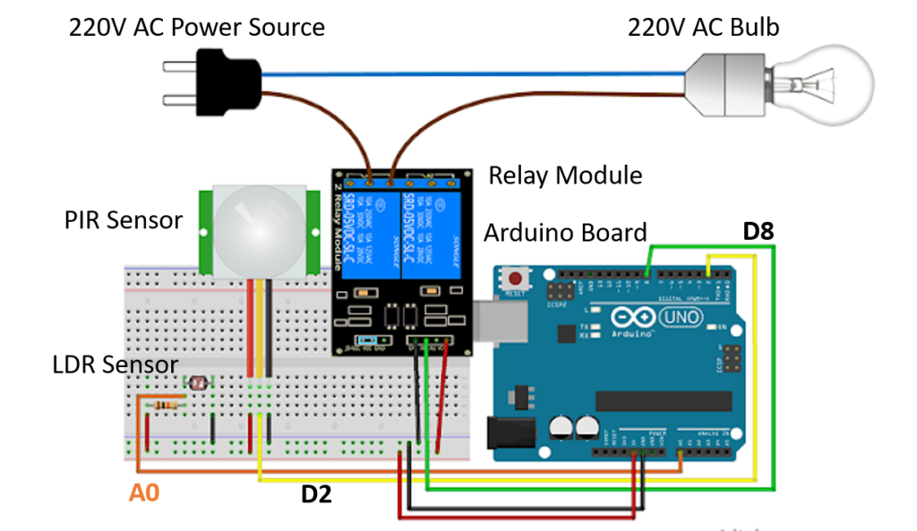
Note: Connect the LED/Bulb (Operating on AC supply) or other lights to the relay module as per its specifications. As there is involvement of 220 – 240V AC power, hence you should make all the connections very carefully.
As we have prepared the circuit of our smart street light Arduino project, next step is to prepare the Arduino code for smart lighting system.
Arduino Code for Smart Street Light Project
The developed Arduino code for this project is given below:
// Relay pin is controlled with D8. The active wire is connected to Normally Closed and common
int relay = 8;
volatile byte relayState = LOW;

// PIR Motion Sensor is connected to D2.
int PIRInterrupt = 2;

// LDR pin is connected to Analog 0
int LDRPin = A0;
// LDR value is stored on LDR reading
int LDRReading;
// LDR Threshold value
int LDRThreshold = 300;

// Timer Variables
long lastDebounceTime = 0;
long debounceDelay = 10000;

void setup() {
  // Pin for relay module set as output
  pinMode(relay, OUTPUT);
  digitalWrite(relay, HIGH);
  // PIR motion sensor set as an input
  pinMode(PIRInterrupt, INPUT);
  // Triggers detectMotion function on rising mode to turn the relay on, if the condition is met
  attachInterrupt(digitalPinToInterrupt(PIRInterrupt), detectMotion, RISING);
  // Serial communication for debugging purposes
  Serial.begin(9600);
}

void loop() {
  // If 10 seconds have passed, the relay is turned off
  if((millis() - lastDebounceTime) > debounceDelay && relayState == HIGH){
    digitalWrite(relay, HIGH);
    relayState = LOW;
    Serial.println("OFF");
  }
  delay(50);
}

void detectMotion() {
  Serial.println("Motion");
  LDRReading = analogRead(LDRPin);
  // LDR Reading value is printed on serial monitor, useful to get your LDRThreshold
  //Serial.println(LDRReading);
  // Only turns the Relay on if the LDR reading is higher than the LDRThreshold
  if(LDRReading > LDRThreshold){
    if(relayState == LOW){
      digitalWrite(relay, LOW);
    }
    relayState = HIGH;
    Serial.println("ON");
    lastDebounceTime = millis();
  }
}
Also Read:
HC-SR04 Arduino: How to use ultrasonic sensor with Arduino
Thin Film Pressure Sensor Arduino (Force Sensor)
The Arduino code for the project is given above, now I am going to explain the flow of the code for your better understanding.
- The PIR sensor is connected to a digital pin (D2) to detect motion.
- The relay module is connected to a digital pin (D8) to control the lights.
- The code continuously monitors the PIR sensor’s output.
- When motion is detected, the lights are turned on using the relay for a specified duration (10 seconds in this example).
- The system turns off the lights when no motion is detected.
Testing of the Street Light Project
Upload the developed code in the Arduino board. Open the serial monitor for better understanding, if sensor is receiving some signal and sending to Arduino.
Make the movement in front of PIR motion sensor to trigger the motion detection. When motion is detected, Arduino will order the LED/Bulb to be ON or OFF according to the PIR signal.
Scope of the Smart Street Light Project
The project focuses on creating a cost-effective and easily implementable solution for homes, offices, or any space where lighting control based on human presence is desirable. The system activates lights when motion is detected, ensuring illumination only when needed, and automatically turns them off when the area is vacant, contributing to energy conservation.
Pingback: How to Build an Automatic Street Light Project with Motion Sensors [PDF Guide] - TechKnowLab