Welcome to another exciting tutorial on Arduino and its vast possibilities! In this blog post, we’ll delve into the fundamental aspects of connecting and controlling a servo motor with Arduino. Servo motors are versatile components commonly used in robotics, automation, and various electronic projects due to their precise control and accurate movement capabilities.
Understanding Servo Motors Arduino
In the vast realm of electronics and robotics, servo motors stand out as crucial components, offering precision, control, and versatility in various applications. In this section, we’ll embark on an introductory journey to understand the fundamental principles and significance of servo motors.
What is a Servo Motor?
At its core, a servo motor is a rotary actuator that allows for precise control of angular position. Unlike standard motors, servo motors are designed to maintain and control a specific position rather than continuous rotation. This unique characteristic makes them indispensable in applications where accurate positioning and controlled movement are paramount.
Operating Principles:
Servo motors operate on a closed-loop control system, meaning they continuously receive feedback about their current position. This feedback loop enables servo motors to make real-time adjustments to their position, ensuring they reach and maintain the desired angle.
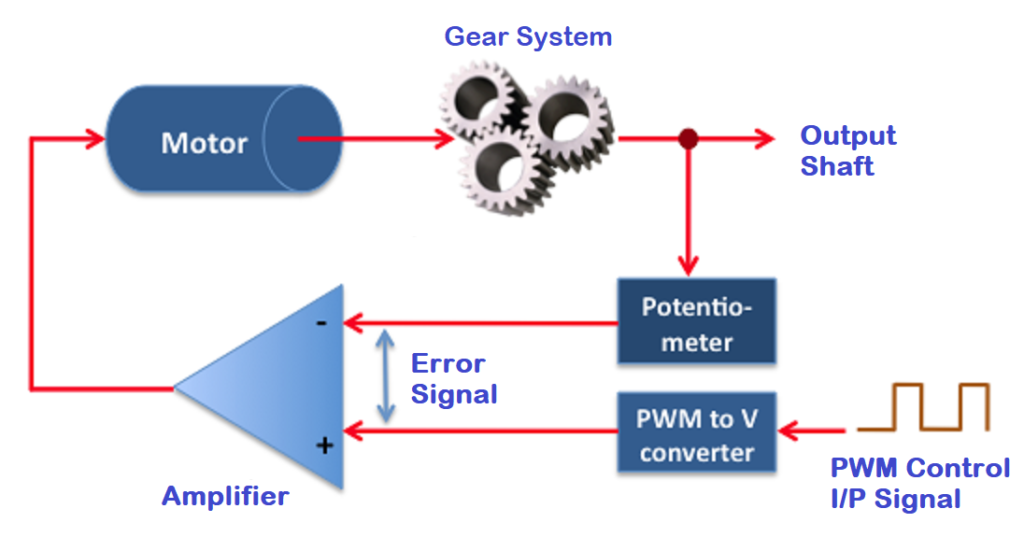
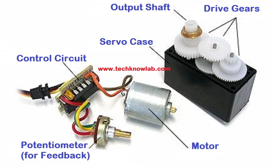
The primary components that enable this closed-loop control are the motor, a position sensor (commonly a potentiometer or an encoder), and a control circuit. The position sensor constantly communicates with the control circuit, providing information about the motor’s current position. The control circuit, in turn, adjusts the motor’s movement to match the desired position, creating a dynamic and accurate control system.
The position of a servo motor is determined by the input signal it receives from a control system. The input signal typically takes the form of a pulse-width modulation (PWM) signal. Here’s how it works:
- Pulse-Width Modulation (PWM):
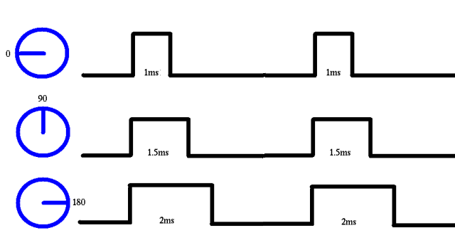
- In a PWM signal, the information is encoded in the width of the pulses. The signal consists of a repeating cycle, and the duration of a specific pulse within that cycle determines the information.
- The pulse width represents a specific position or angle that the servo motor should move to. Typically, the pulse width is measured in milliseconds.
- Pulse Cycle:
- The entire PWM cycle consists of a series of pulses, and the cycle repeats at a regular interval.
- The frequency of the PWM signal is usually constant, and the width of a particular pulse within the cycle varies to convey the desired position.
- Neutral Position:
- The neutral or center position of the servo motor is usually represented by a pulse width of around 1.5 milliseconds. In this position, the motor is not actively moving, and it is considered the reference point.
- Directional Information:
- The direction of rotation can be determined by whether the pulse is shorter or longer than the neutral pulse. For example, a pulse shorter than 1.5 milliseconds might indicate a movement in one direction, while a longer pulse might indicate movement in the opposite direction.
- Range of Motion:
- The range of motion of the servo motor is often specified by the manufacturer and is influenced by the pulse widths. For example, a servo motor might be designed to rotate 90 degrees to either side of the neutral position, corresponding to shorter or longer pulse widths.
- Feedback Mechanism:
- The servo motor continuously monitors its actual position through a feedback device, such as a potentiometer or an encoder.
- The feedback information is compared with the desired position encoded in the PWM signal, and any difference (error) between the two is used to adjust the motor’s position.
- Closed-Loop Control:
- The system operates in a closed-loop control manner, where the control circuit adjusts the motor’s position based on the feedback until the desired position is reached.
Types of Servo Motors:
Servo motors come in various types, each tailored to specific applications:
- Positional Servo Motors:
- These are the most common servo motors used for precise angular positioning.
- Ideal for applications where a defined range of motion is required.
- Continuous Rotation Servo Motors:
- Unlike standard servos, these can rotate continuously.
- Suitable for applications where continuous motion is necessary, such as robotics.
- Micro Servo Motors:
- Compact in size, these servos are suitable for projects with limited space.
- Commonly used in miniature robotic applications and model aircraft.
Understanding these types of servo motors provides a foundation for selecting the right one based on the specific requirements of your project.
Servo motors play a pivotal role in the world of electronics and robotics, providing a precise and controllable means of achieving motion. In the following sections, we’ll delve into the practical aspects of connecting a servo motor to an Arduino and explore the fascinating realm of servo motor control. So, buckle up as we embark on a journey into the basics of controlling servo motors with Arduino!
Components You’ll Need
Now that we’ve established a foundational understanding of servo motors [Servo Motors Arduino], let’s move on to the practical side of things. In this section, we’ll explore the essential components you’ll need to bring your servo motor to life and interface it with an Arduino.
- Arduino Board (e.g., Arduino Uno)
- Servo Motor
- Jumper Wires
- Breadboard
- Power Supply
- Potentiometer
At the core of your project is the Arduino board, with the Arduino Uno being a widely chosen option due to its user-friendly interface, strong community support, and compatibility with the Arduino Integrated Development Environment (IDE). Make sure to have your Arduino board at hand as you embark on your project. When selecting a servo motor, carefully consider factors such as torque, speed, and physical size, ensuring it aligns with your project’s goals—whether you need a standard servo for precise movements or a continuous rotation servo for constant spinning. Jumper wires play a crucial role in connecting components on a breadboard or linking them to the Arduino board, so have a set of male-to-male and male-to-female jumper wires ready for an organized circuit setup. A breadboard serves as a key component for prototyping and creating temporary circuits without soldering, so verify its cleanliness and functionality before beginning your project.
If your project involves multiple servo motors or requires more power than the Arduino can provide, consider employing an external power supply for stable and reliable operation. Additionally, for projects requiring dynamic control of the servo motor, a potentiometer can be a valuable addition, allowing manual adjustment of the servo’s position.
Before diving into the wiring and coding, gather all your components in a well-lit and organized workspace. Having everything within reach will streamline the assembly process and minimize interruptions.
In the next sections, we’ll guide you through the step-by-step process of wiring the circuit and writing the Arduino code to control your servo motor effectively. Let’s turn these components into a functional and exciting project!
Circuit for Servo Motor Arduino
Wiring the circuit is a crucial step in bringing your servo motor and Arduino together. A well-organized and correctly connected circuit ensures smooth communication between components. Follow these steps, accompanied by clear illustrations, to set up your servo motor circuit.
Step-by-Step Guide with Clear Illustrations:
Step 1: Place the Arduino Board and Breadboard
Begin by placing your Arduino board and breadboard on your workspace. Ensure they are close enough for easy connections with jumper wires.
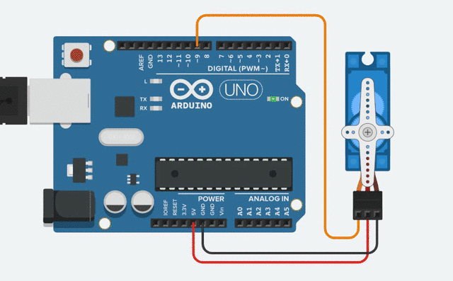
Step 2: Connect the Servo Motor Arduino
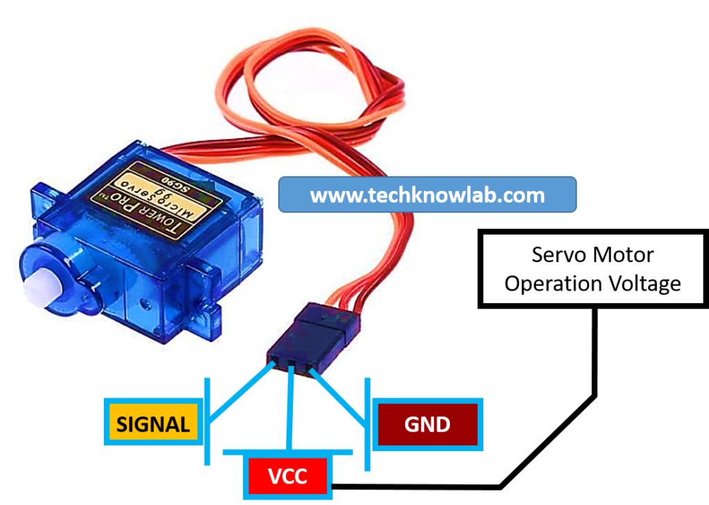
- Identify the three wires of your servo motor: Power/VCC (usually red), ground (usually brown), and control/control (usually orange or yellow).
- Connect the power wire to the 5V pin on the Arduino (red wire).
- Connect the ground wire to any GND (ground) pin on the Arduino (brown wire).
- Connect the control wire to a digital pin on the Arduino (e.g., pin 9) using a jumper wire (orange or yellow wire).
Step 3: Power the Arduino
Connect the Arduino to your computer using a USB cable to provide power to the board.
Step 4: Verify Your Wiring
Double-check all connections to ensure they are secure and correctly placed. Mistakes at this stage can lead to unexpected behavior in your servo motor.
Pin Connections between Arduino and Servo Motor:
Understanding the pin connections is crucial for successful communication between the Arduino board and the servo motor. Here’s a breakdown:
- Arduino Pin 5V → Servo Power
- Arduino GND → Servo Ground
- Arduino Digital Pin (e.g., 9) → Servo Control
Explaining Power and Ground Connections:
- The 5V pin on the Arduino provides power to the servo motor, ensuring it has the necessary voltage to operate.
- The GND (ground) pin on the Arduino establishes a common ground reference between the Arduino and the servo motor, ensuring a stable electrical connection.
- The control wire allows the Arduino to send signals to the servo motor, instructing it on the desired position.
With these connections, your servo motor is now integrated into the Arduino circuit. In the upcoming section, we’ll explore how to write the Arduino code to control the servo motor’s movement. Let’s bring your project to life through coding!
Writing Arduino Code for Servo Motor Arduino
Now that your servo motor is correctly wired to the Arduino, let’s move on to writing the Arduino code. This code will instruct the Arduino on how to control the servo motor’s movement. Follow this step-by-step guide to create a basic Arduino code for servo motor control.
Initialization and Servo Library Inclusion:
#include <Servo.h>
Servo myServo;  // create servo object to control a servo
Explain that these lines are initializing the Servo library, a crucial step for interfacing with servo motors. The myServo object is then created to control the servo motor.
Setting up the Servo Object
void setup() {
  myServo.attach(9);  // attaches the servo on pin 9
}
In the setup() function, the myServo object is attached to a specific digital pin on the Arduino. In this example, it’s attached to pin 9. Ensure that the pin number specified matches the pin to which you connected the control wire of the servo.
Code for Basic Movements (e.g., 90-Degree Rotation)
void loop() {
  myServo.write(90);  // moves the servo to 90 degrees
  delay(1000);        // waits for a second
  myServo.write(0);   // moves the servo to 0 degrees
  delay(1000);        // waits for a second
}
This loop() function contains the basic code for moving the servo motor. The myServo.write(90) command instructs the servo to move to a 90-degree position, and the delay(1000) pauses the program for one second. The subsequent lines command the servo to move to 0 degrees and introduce another one-second delay.
Explanation of Code Structure:
Provide a breakdown of the code structure:
myServo.write(90)andmyServo.write(0): These lines control the servo motor’s position. The argument passed towrite()specifies the desired angle in degrees.delay(1000): This command introduces a delay in milliseconds. In this case, it pauses the program for one second.
Explain that this basic code snippet creates a simple back-and-forth movement for the servo motor. Encourage readers to experiment with different angles and timings to observe how the servo responds.
Now, your Arduino is ready to execute the commands and control the servo motor. In the upcoming sections, we’ll test the setup and explore ways to expand your knowledge in servo motor control. Let’s move forward and witness your servo motor in action!
Testing the Setup
Testing the setup is a critical step to ensure that your servo motor responds as expected to the commands given by the Arduino. In this section, we’ll guide you through the testing process and provide tips for troubleshooting common issues.
Tips for Troubleshooting:
Before initiating the test, here are some tips to address potential issues:
- Check Wiring Connections:
- Ensure that all wires are securely connected to the correct pins on both the Arduino and the servo motor. A loose connection can lead to erratic behavior.
- Verify Power Supply:
- Confirm that the power supply to the servo motor is stable. If using an external power source, check its voltage and current ratings.
- Inspect the Code:
- Double-check your Arduino code for any syntax errors or logical issues. Ensure that the pin numbers in the code match the physical connections.
- Review Servo Specifications:
- Refer to the specifications of your specific servo motor to ensure it’s compatible with the Arduino and can handle the power supplied.
Common Issues and Solutions:
- Jittery Movements:
- Solution: Increase the delay between movements in your code. Jittery movements can occur if the servo doesn’t have sufficient time to reach the desired position.
- Servo Not Moving:
- Solution: Check the power supply to the servo motor. Ensure that the servo is receiving power from the correct pin on the Arduino.
- Unusual Sounds or Overheating:
- Solution: If you’re using an external power source, check if it’s providing the correct voltage. Servo motors may make unusual sounds or overheat if the voltage is too high.
Adjusting Servo Range if Needed:
If you find that the servo motor’s movement range is not aligning with your project requirements, you can adjust the angles in the Arduino code. Modify the myServo.write() commands with the desired angles in degrees.
For example, if you want the servo to have a range of 45 to 135 degrees, you can modify the code as follows:
void loop() {
  myServo.write(45);  // moves the servo to 45 degrees
  delay(1000);        // waits for a second
  myServo.write(135);  // moves the servo to 135 degrees
  delay(1000);        // waits for a second
}
Experiment with different angles to achieve the desired range of motion.
With these tips in mind, proceed to test your setup. Upload the code to your Arduino board, open the Serial Monitor in the Arduino IDE to check for any potential error messages, and observe the behavior of your servo motor. If everything is working smoothly, congratulations! Your servo motor is successfully connected and controlled by the Arduino.
In the next section, we’ll explore ways to expand your knowledge by incorporating potentiometers for dynamic control. Get ready to take your servo motor project to the next level!
Expanding Your Knowledge of Servo Motor Arduino
Congratulations on successfully testing your servo motor setup! Now, let’s explore ways to expand your knowledge and enhance your servo motor project with additional features and functionalities.
1. Incorporating Potentiometers for Dynamic Control:
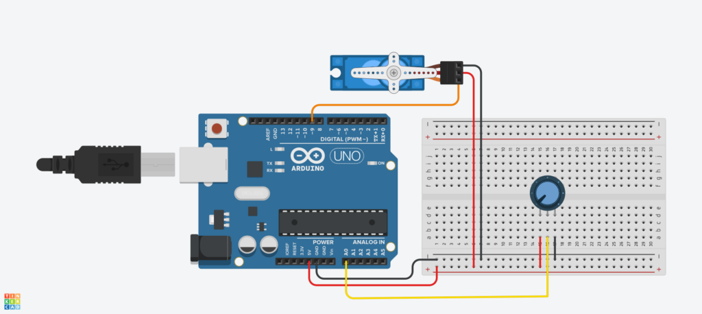
Potentiometers, or variable resistors, can be integrated into your project to allow dynamic control of the servo motor’s position. This adds an interactive element, enabling users to manually adjust the servo’s angle.
Components Needed:
- Potentiometer
- Jumper wires
Wiring the Potentiometer:
- Connect one end of the potentiometer to the 5V pin on the Arduino.
- Connect the other end to the GND (ground) pin on the Arduino.
- Connect the middle pin of the potentiometer to an analog pin on the Arduino (e.g., A0).
Modifying the Arduino Code
#include <Servo.h>

Servo myServo;      // create servo object to control a servo
int potPin = A0;     // analog pin to which the potentiometer is connected

void setup() {
  myServo.attach(9);  // attaches the servo on pin 9
}

void loop() {
  int potValue = analogRead(potPin);  // read the potentiometer value
  int servoPos = map(potValue, 0, 1023, 0, 180);  // map potentiometer value to servo angle
  myServo.write(servoPos);  // move the servo to the mapped position
  delay(15);  // add a slight delay for smoother control
}
Explanation:
- The potentiometer’s analog value is read using
analogRead(). - The
map()function scales the analog reading (ranging from 0 to 1023) to a servo angle (ranging from 0 to 180 degrees). - The servo is then moved to the calculated position.
Now, turning the potentiometer will dynamically control the servo motor’s position. This opens up possibilities for interactive projects and user-controlled applications.
2. Using External Power Sources for Multiple Servos:
When working with multiple servo motors or power-hungry servos, using an external power source becomes necessary. This ensures that the Arduino’s power supply is not overloaded.
Components Needed:
- External power supply (appropriate voltage and current rating)
- Diode (to protect against voltage spikes)
Wiring the External Power Supply:
- Connect the positive (+) terminal of the external power supply to the servo motors.
- Connect the negative (-) terminal of the external power supply to the ground (GND) on the Arduino.
- Connect the ground (GND) of the external power supply to the servo motors and the ground rail on the breadboard.
Code Adjustment:
No specific code adjustments are needed for using an external power source. However, always ensure that the ground of the external power supply is connected to the Arduino’s ground.
3. Advanced Servo Motor Arduino Control Techniques:
For more advanced projects, consider exploring techniques such as PID (Proportional-Integral-Derivative) control. PID control provides a way to achieve precise and stable servo motor control by adjusting the proportional, integral, and derivative terms.
Implementation:
Implementing PID control involves complex algorithms and goes beyond the scope of a basic tutorial. However, resources and libraries are available that simplify the integration of PID control into Arduino projects. Consider exploring PID libraries and guides to enhance your servo control capabilities.
By incorporating potentiometers, using external power sources, and exploring advanced control techniques, you’ve expanded your knowledge of servo motor interfacing with Arduino. Feel free to experiment further and combine these techniques to create innovative and dynamic projects.
In the next section, we’ll recap the key points of the tutorial and encourage you to continue exploring the vast possibilities of Arduino and servo motors.
Top 10 Servo Motor Arduino Projects
Servo motors, coupled with Arduino, open the door to a myriad of exciting projects. Here are ten project ideas to spark your creativity:
- Automated Plant Watering System:
- Use a soil moisture sensor to detect when plants need watering.
- Connect a servo motor to control a water valve and automate the watering process.
- Pan-and-Tilt Camera Mount:
- Build a pan-and-tilt camera mount using two servo motors.
- Control the movement of the mount to capture images or videos in different directions.
- Gesture-Controlled Robot Arm:
- Attach a robotic arm with servo motors to a robot chassis.
- Implement a gesture recognition system using sensors (e.g., accelerometer or gyroscope) to control the robot arm.
- Door Lock System:
- Create a door lock system using a servo motor to control a locking mechanism.
- Implement a keypad or RFID module for secure access.
- Automated Pet Feeder:
- Design an automated pet feeder with a servo motor to dispense pet food.
- Schedule feeding times or trigger feeding remotely using a mobile app.
- Solar Tracker:
- Build a solar tracker system with servo motors to orient solar panels towards the sun.
- Maximize energy harvesting by ensuring panels follow the sun’s movement.
- Interactive Gaming Console:
- Construct a simple gaming console with a servo-controlled paddle.
- Use sensors to detect the movement of the player and control the paddle in a game.
- Animated Halloween Props:
- Create spooky animated props for Halloween using servo motors.
- Control the movement of skeletons, witches, or other props to add a dynamic element to your decorations.
- Weather Station with Moving Display:
- Build a weather station that displays weather conditions using a servo-controlled display.
- Use sensors to measure temperature, humidity, and other weather parameters.
- Automated Blinds or Curtains:
- Install servo motors to automate the opening and closing of blinds or curtains.
- Implement light sensors or a timer to control the operation based on ambient light conditions.
Remember, these project ideas are starting points. Feel free to mix and match components, add sensors, and incorporate other technologies to make them uniquely yours.
Conclusion
Congratulations on completing the “Servo Motor to Arduino – Servo Motor Control Basics” tutorial! You’ve gained valuable insights into the world of servo motors, Arduino, and the fundamental principles of their integration. Let’s recap what you’ve learned and encourage you to continue your exploration in this exciting field.
Key Takeaways:
- Understanding Servo Motors:
- Explored the basic principles of servo motors, their operating mechanisms, and different types available.
- Components You’ll Need:
- Identified the essential components, including the Arduino board, servo motor, jumper wires, and breadboard, required for the project.
- Wiring the Circuit:
- Followed a step-by-step guide to connect the servo motor to the Arduino, ensuring proper power and ground connections.
- Writing Arduino Code:
- Created an Arduino code to control the servo motor’s movement, including initialization, setting up the servo object, and writing basic movements.
- Testing the Setup:
- Learned tips for troubleshooting common issues and ensuring a smooth testing process.
- Expanding Your Knowledge:
- Explored advanced topics such as incorporating potentiometers for dynamic control, using external power sources for multiple servos, and delved into the potential of advanced servo control techniques like PID.
Your Next Steps:
- Experiment and Tinker:
- Don’t stop here! Continue experimenting with different servo angles, timings, and coding techniques to deepen your understanding.
- Explore Further Applications:
- Consider integrating servo motors into more complex projects, such as robotic arms, automated systems, or interactive installations.
- Connect with the our Community:
- Join our communities, and social media groups dedicated to Arduino and electronics. Share your projects, ask questions in the comments, and learn from others.
- Continue Learning:
- Stay updated on the latest developments in Arduino and servo motor technology. Explore more advanced coding techniques and delve into other sensors and actuators.
Final Thoughts:
The journey of learning Arduino and servo motor control is an ongoing adventure. Your newfound knowledge provides a solid foundation for tackling more ambitious projects and exploring the vast possibilities that this dynamic field offers.
Remember, the most significant discoveries often come from hands-on experimentation and a curious mindset. Keep innovating, building, and enjoying the process of bringing your ideas to life.
Happy tinkering, and may your future projects be filled with success and creativity!
Pingback: Automatic Wire Cutting Tool - TechKnowLab