WiFi Controlled Car: Hi Readers! Welcome to this new article. Today in this article, I am going to share with you, How to make a WIFI controlled car using ESP8266 or Nodemcu and Blynk App. All the 3D models, circuit Diagram and Arduino code have been included in this article.
WIFI Controlled Car
The main objective of this project is to remotely control the a car through wifi. For the same purpose, I am going to use Blynk Application for creating GUI and connect it with NodeMCU/ESP8266 micro-controlle for communication through the internet.
It will also answer you question like – How to control DC motor with L298n driver using blynk IoT and ESP8266? or How to make a car using NodeMCU?
The body of the car is 3D printed using PLA and TPU material. The complete project is divided in three steps:
1 – 3D CAD Modelling and 3D Printing of Parts
2 – Electronics components assembly and Circuit Diagram
3 – Arduino Code for WIFI controlled car using ESP8266 or Nodemcu
WIFI Controlled Car – 3D Models/STL files
The parts used in this project are modeled using Fusion 360 and 3D printed using FFF 3D Printer (with PLA and TPU Material.

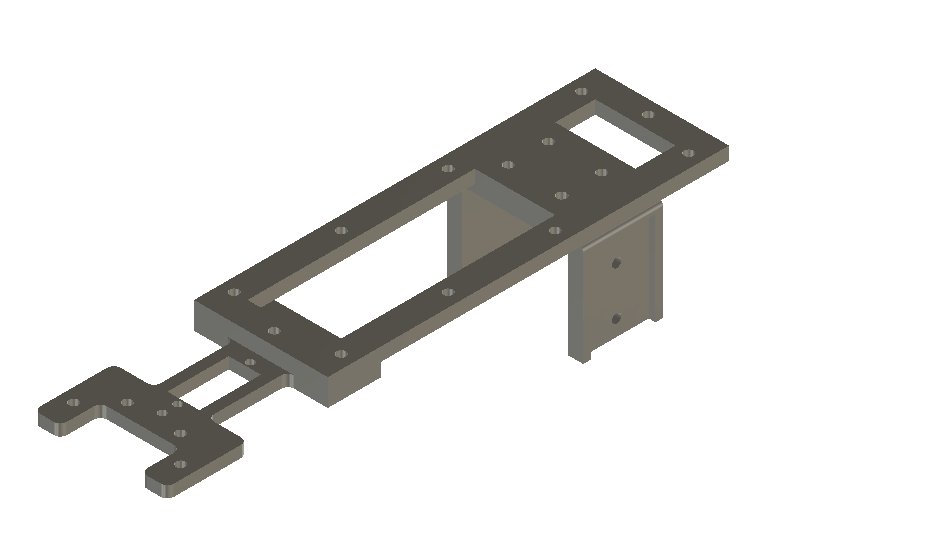


If you want to download the STL files of all the components used in this WIFI controlled car using ESP8266 or Nodemcu and Blynk App, you can visit the following links:
Thingiverse – wifi remote control car STL files
Cults3D – wifi controlled rc car STL Files
Also Read: Automatic Wire Cutting Tool
Electronics components assembly and Circuit Diagram – WIFI Controlled Car
I am listing all the electronics components used in this wifi remote control car, below :
💡 Note: As an Amazon Associate, I earn from qualifying purchases. This helps me keep creating valuable content without any additional cost to you.
Now we have to assemble all the electronics components according to the circuit diagram. I am providing you the circuit diagram for this wifi rc car below. You can go through it carefully and make the connections properly.
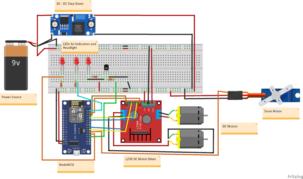
The circuit diagram, I have provided above can also be used to learn – How to control DC motor with L298n driver using blynk IoT and ESP8266.
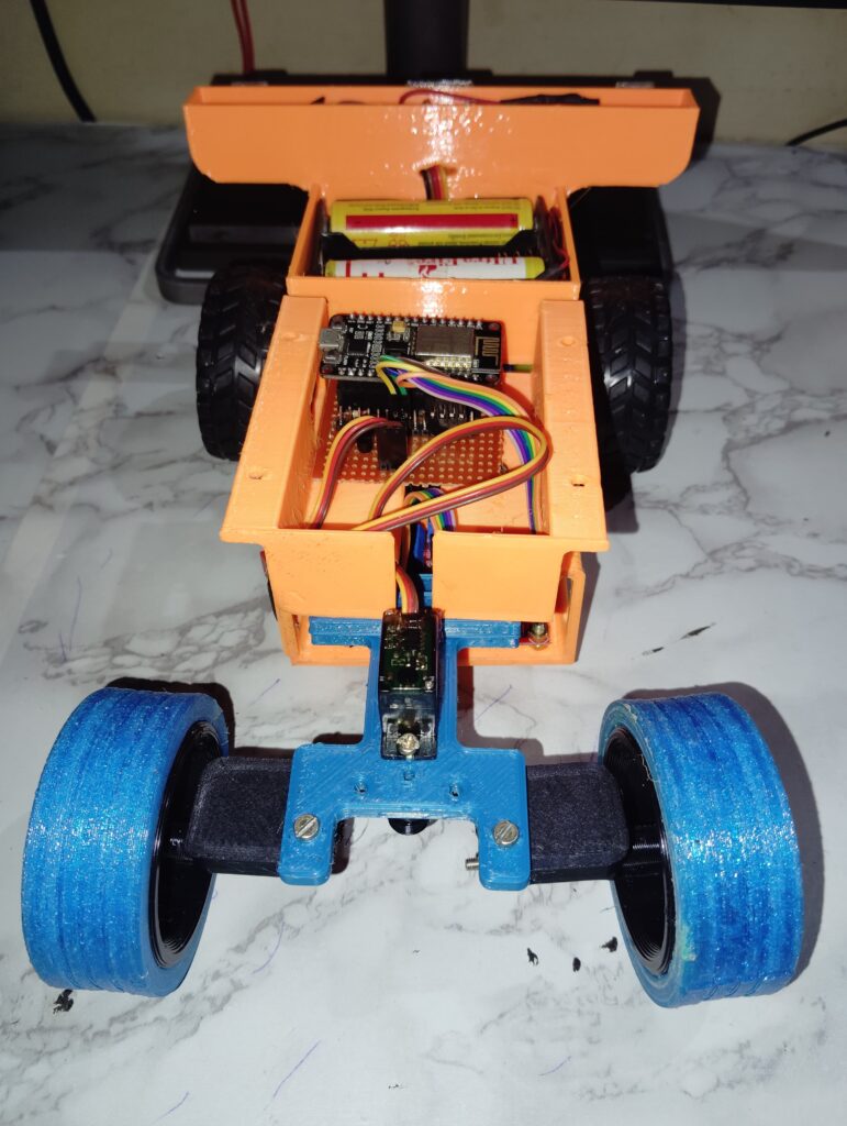
Now our mechanical assembly is ready and we have also prepared the circuit and assembled all the electronics components. Ab bas isme aatma dalni hai! (Body is ready, Only soul is remaining in this RC Car). Aatma of this RC car is Arduino code.
Arduino Code for WIFI controlled car using ESP8266 or NodeMCU
I am attaching the Arduino code for this WiFi Car below.
#include <Servo.h>

#define BLYNK_PRINT Serial
#define BLYNK_TEMPLATE_ID "Your_tempelat_ID"
#define BLYNK_TEMPLATE_NAME "Tempelate_name"
#define BLYNK_AUTH_TOKEN "Your_Auth_Token"

#include <ESP8266WiFi.h>
#include <BlynkSimpleEsp8266.h>


// Blynk Auth Token
char auth[] = "Your_Auth_Token";

// WiFi credentials
char ssid[] = " ";
char pass[] = " ";

// Motor driver pins
const int ENA = 5;  // PWM pin for speed control
const int IN1 = 0;  // IN1 for Motor A
const int IN2 = 2;  // IN2 for Motor A

const int ENB = 4;  // PWM pin for speed control
const int IN3 = 14; // IN3 for Motor B
const int IN4 = 12; // IN4 for Motor B

// Servo pin
const int servoPin = 13;
Servo steeringServo;

// LED pins
const int indicatorLeft = 16;
const int indicatorRight = 15;
const int headlight = 3;

bool forward = 0;
bool backward = 0;
int Speed;

BLYNK_WRITE(V1) {  // Virtual pin V1 for motor speed and direction control
  Speed = param.asInt();

}

BLYNK_WRITE(V2) {  // Virtual pin V2 for steering control via potentiometer knob
  int angle = param.asInt();  // Read the value from the Blynk app knob
  steeringServo.write(angle);
}

// BLYNK_WRITE(V3) {  // Virtual pin V3 for left indicator
//   int state = param.asInt();
//   digitalWrite(indicatorLeft, state);
// }

// BLYNK_WRITE(V4) {  // Virtual pin V4 for right indicator
//   int state = param.asInt();
//   digitalWrite(indicatorRight, state);
// }

BLYNK_WRITE(V5) {  // Virtual pin V5 for headlight
  int state = param.asInt();
  digitalWrite(headlight, state);
}

BLYNK_WRITE(V3) {
  forward = param.asInt();
}

BLYNK_WRITE(V4) {
  backward = param.asInt();
}

void smartcar() {
  if (forward == 1) {
    carforward();
    Serial.println("carforward");
  } else if (backward == 1) {
    carbackward();
    Serial.println("carbackward");
  } else if (forward == 0 && backward == 0) {
    carStop();
    Serial.println("carstop");
  }
}

void setup() {
  Serial.begin(9600);
  Blynk.begin(auth, ssid, pass, "blynk.cloud", 80);

  // Setup motor driver pins
  pinMode(ENA, OUTPUT);
  pinMode(IN1, OUTPUT);
  pinMode(IN2, OUTPUT);
  pinMode(ENB, OUTPUT);
  pinMode(IN3, OUTPUT);
  pinMode(IN4, OUTPUT);

  // Setup servo
  steeringServo.attach(servoPin);

  // Setup LEDs
  pinMode(indicatorLeft, OUTPUT);
  pinMode(indicatorRight, OUTPUT);
  pinMode(headlight, OUTPUT);
}

void loop() {
  Blynk.run();
  smartcar();
}

void carforward() {
  analogWrite(ENA, Speed);
  analogWrite(ENB, Speed);
  digitalWrite(IN1, LOW);
  digitalWrite(IN2, HIGH);
  digitalWrite(IN3, HIGH);
  digitalWrite(IN4, LOW);
}
void carbackward() {
  analogWrite(ENA, Speed);
  analogWrite(ENB, Speed);
  digitalWrite(IN1, HIGH);
  digitalWrite(IN2, LOW);
  digitalWrite(IN3, LOW);
  digitalWrite(IN4, HIGH);
}
void carStop() {
  digitalWrite(IN1, LOW);
  digitalWrite(IN2, LOW);
  digitalWrite(IN3, LOW);
  digitalWrite(IN4, LOW);
}
You can upload this Arduino code to the assembled WiFi car. Now Our car is ready to Race!

Conclusion
Our WiFi controlled car is ready. I hope you have learned How to make a WIFI controlled car using ESP8266 or Nodemcu and Blynk App. If you have further any question or want to me help you, we can start the discussion below in the comment section.
Happy Tinkering!