DIY Automatic Wire Cutting: Many times you may need to cut the wire into small pieces/pellets. Here, in this blog article, I am going to show you, how I build a DIY Automatic Wire Cutting Tool. This article will guide you on how to assemble, design, and fabricate various parts and interface electronics components to make a wire-cutting machine.
Introduction
There is a story behind the development of this tool. I have to experiment, for my research. In my experiment, I needed pellets/granules from the filament (FDM-based 3D printing material). Hence, I started to cut the filaments manually using a wire cutter. But, this was very time-consuming and tedious work. Additionally, the length of the pellets was not uniform. Therefore, I thought of making a tool that could cut the filaments in pellets with uniform and accurate lengths. The idea was realized and the result is in front of you.
Components Required for Automatic Wire Cutting
To make the automatic wire-cutting tool, the following components have been used:
- Arduino (UNO/MEGA 2650/Nano, etc.)
- Servo motor/DC Motor
- Stepper Motor
- Extruder Kit
- A4988 Stepper driver
- Wire Cutter
- 3D Printed Parts
- Nut-Bolt and other spare parts
Working Principle
Manually wire is cut using a mechanical cutter (scissor). The main objective of this project is to automatically operating the mechanical without human effort. Therefore, there is need of an actuator which can provide motion to cutter to cut the wire.
Servo Motor v/s Simple DC Motor
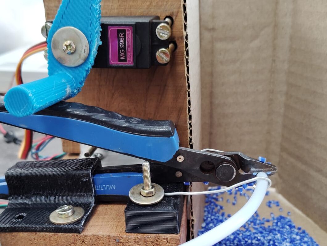
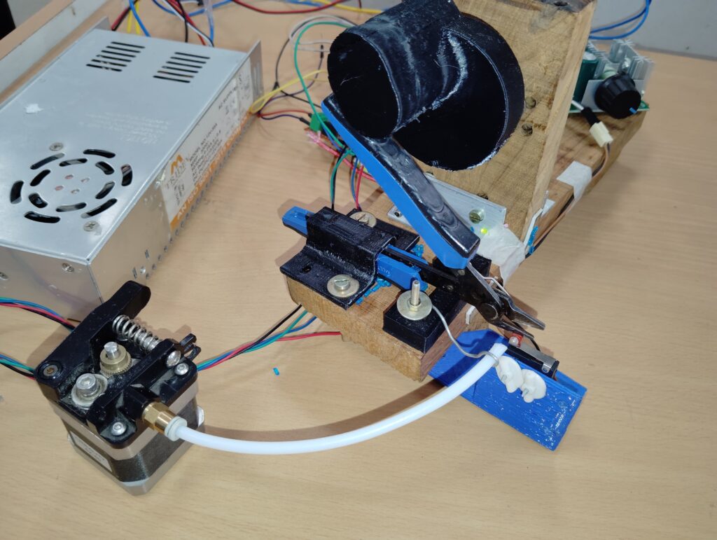
In the first attempt, I have used servo motor as actuator but later I found that the servo motor (in my inventory) has not sufficient torque to operate the cutter. My servo motor damaged due to over load. Cutting speed was also slow due to servo motor.

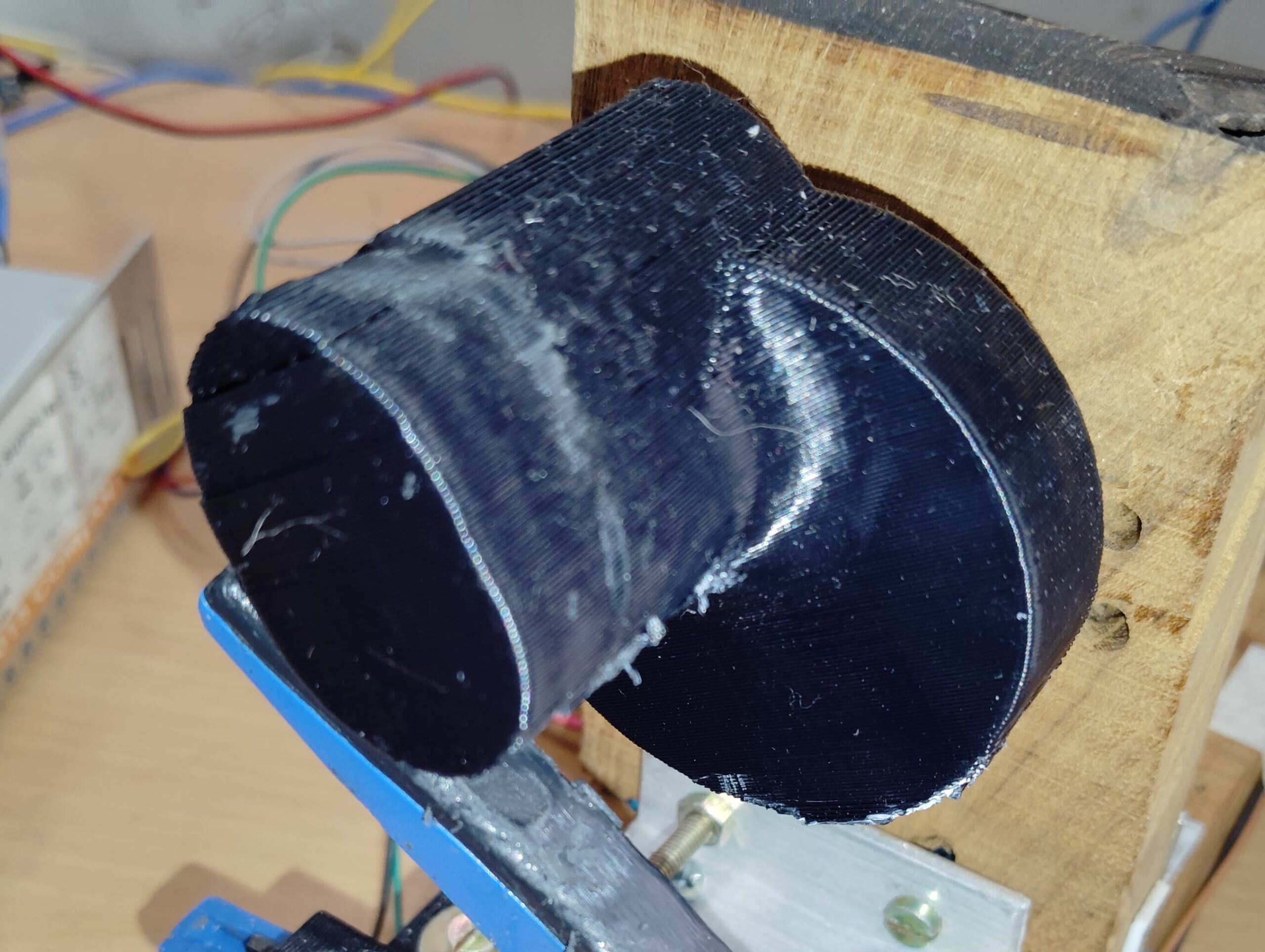
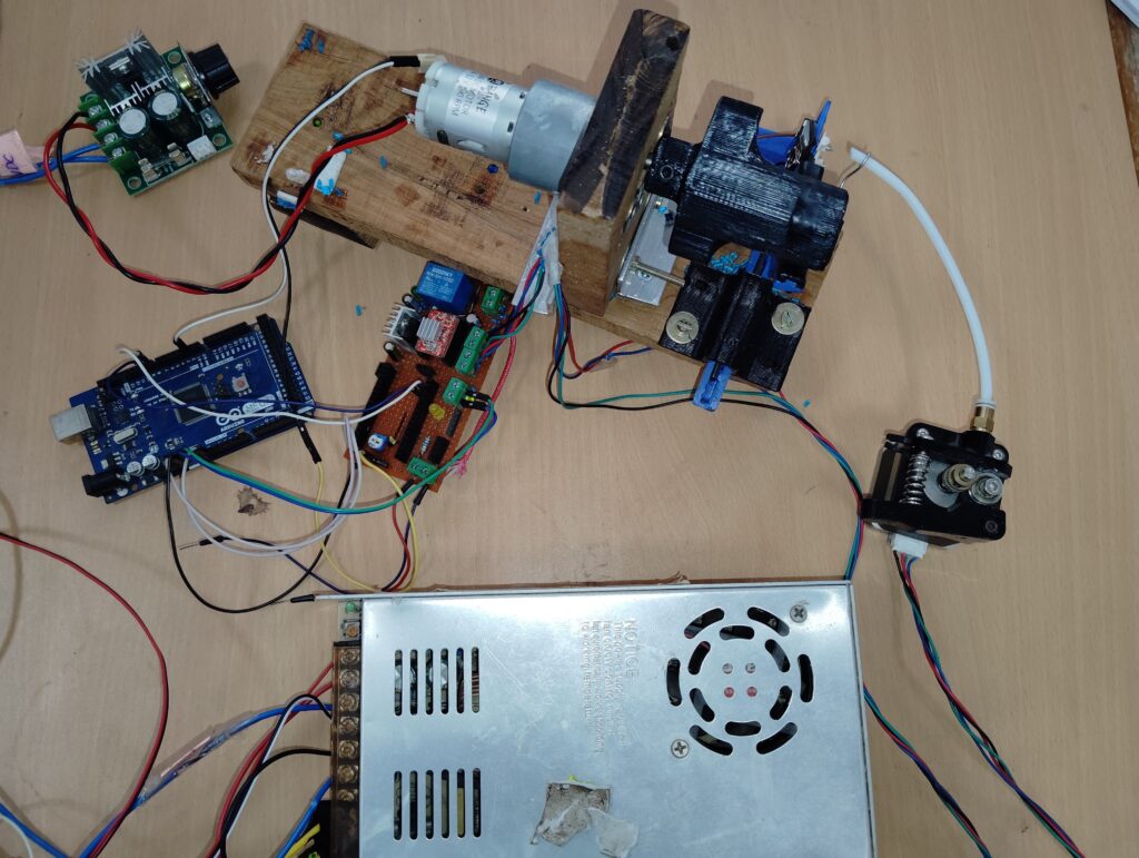
To solve the above issue, I replaced the servo motor with a high torque (100RPM,12V) simple DC motor. You can see both the motors in the image given above.
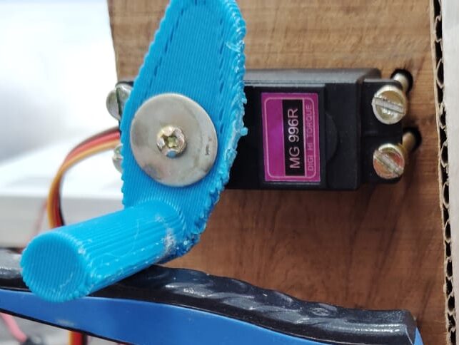
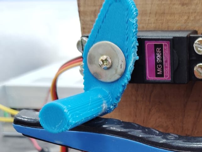
Push Lever
As we know servo motor is more precise and we can control at what angle we have to rotate it. On the other hand without using encoder it is not possible to control the angle of rotation of a DC motor. DC motor will rotate continuously. Therefore, I have to design two different push lever for both the motors. The push lever is attached with the shaft, which is rotated to push the cutter.
Role of Extruder Kit in Automatic Wire Cutter
3D Printer extruder kit is an assembly of stepper motor, spring loaded wheel against the grooved wheel mounted on motor shaft, and a bowden tube. I have used this 3D printer extruder kit to feed the wire inside the mechanical cutter.
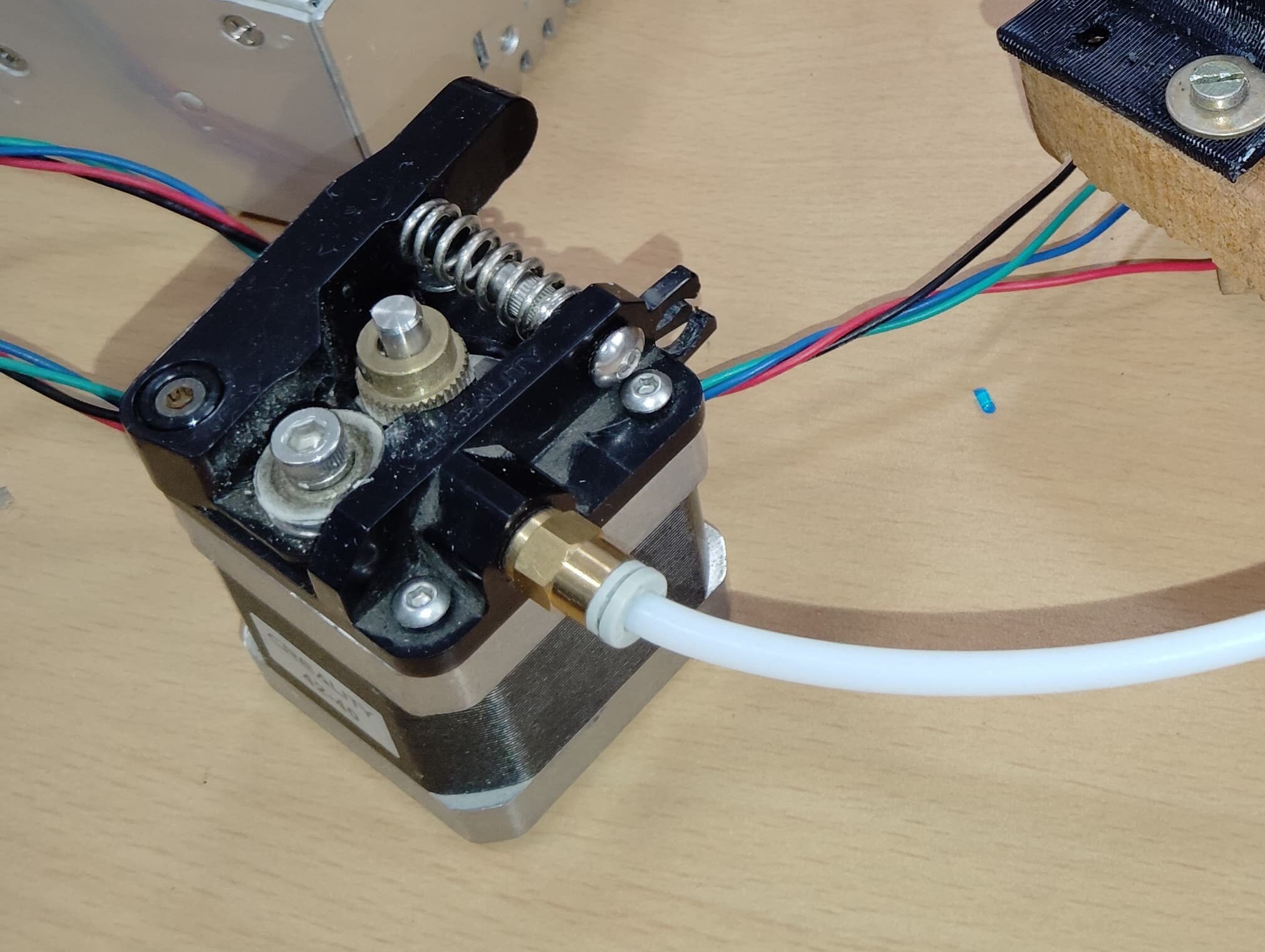
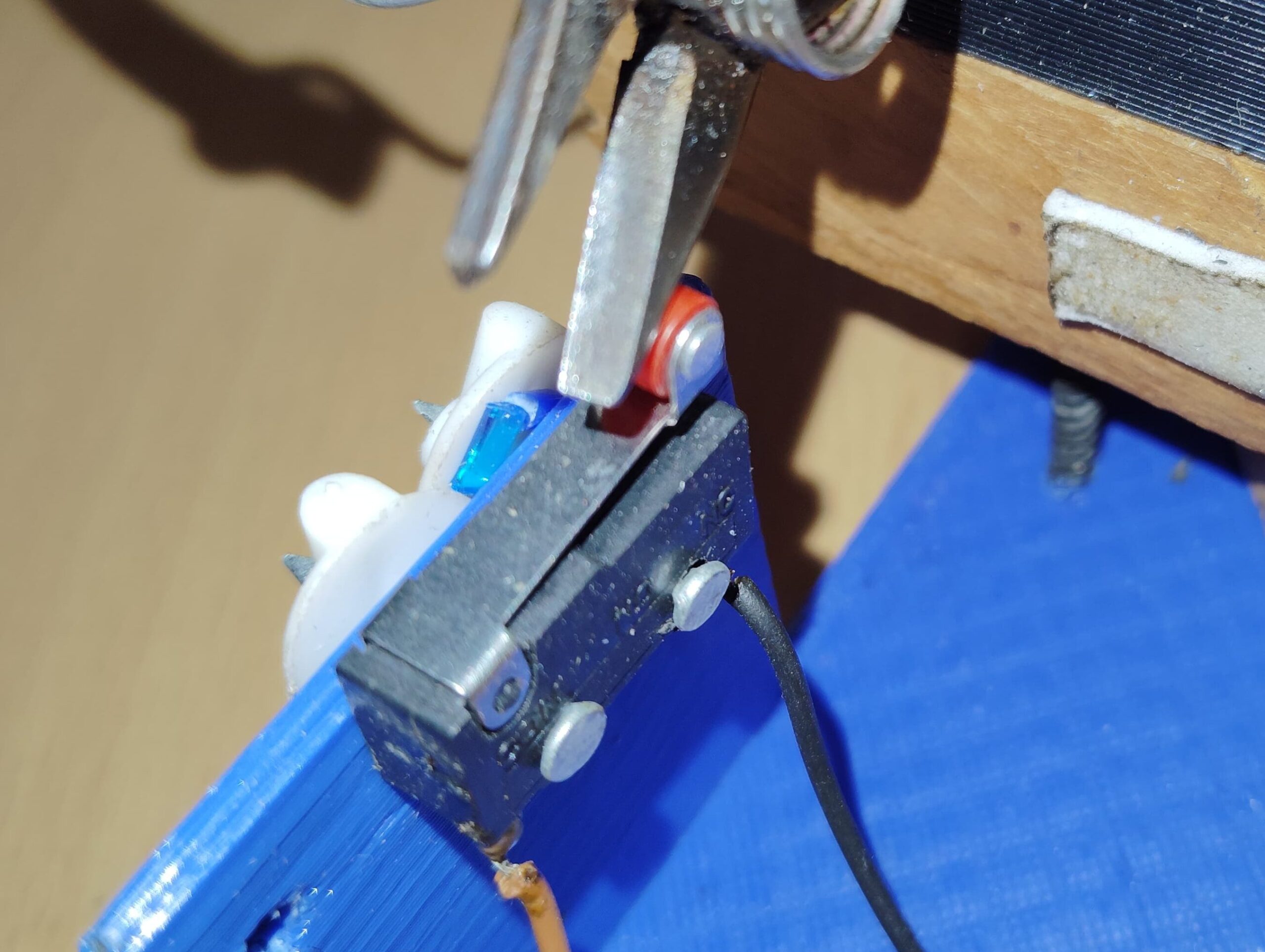
The length of the pellets/pieces is dependent on the speed and fee duration of stepper motor. If speed is slow the length of the pellet is small. If we increase the speed the length of piece also increases. I have used a limit switch to activate the feed duration of motor.
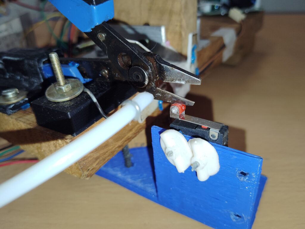
When the mouth of cutter is open it presses the limit switch, which signals the micro controller to feed the wire inside the mouth of the cutter using stepper motor.
Base structure of Automatic Wire Cutting
I have installed all the components like, cutter, Servo/DC motor, and other electronics on a base structure. I have used wooden plank to make this base structure. I also designed and 3D printed some brackets to fix the cutter firmly, on the base structure.
Also read: Temperature based Fan Speed Control using Arduino
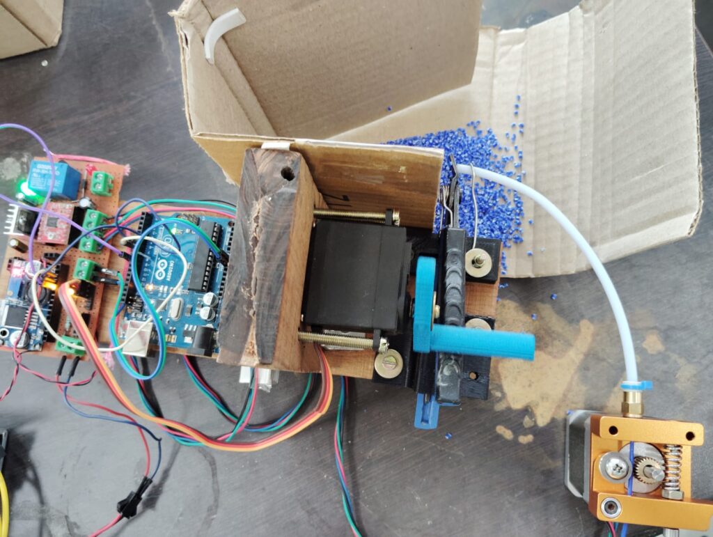
Electronics components and Circuit Diagram for Automatic Wire Cutter
In this automatic wire cutting system, I have already discussed all the mechanical parts that make the system work. Now it’s time to understand the electrical system, or rather the electronic system. In this section, we will go over the circuit diagram and how to interface all the electronic components we are going to use. This includes how to interface the limit switch with the microcontroller, how to interface the stepper motor with the microcontroller, and how to control the DC motor. We will cover all these aspects in this section.
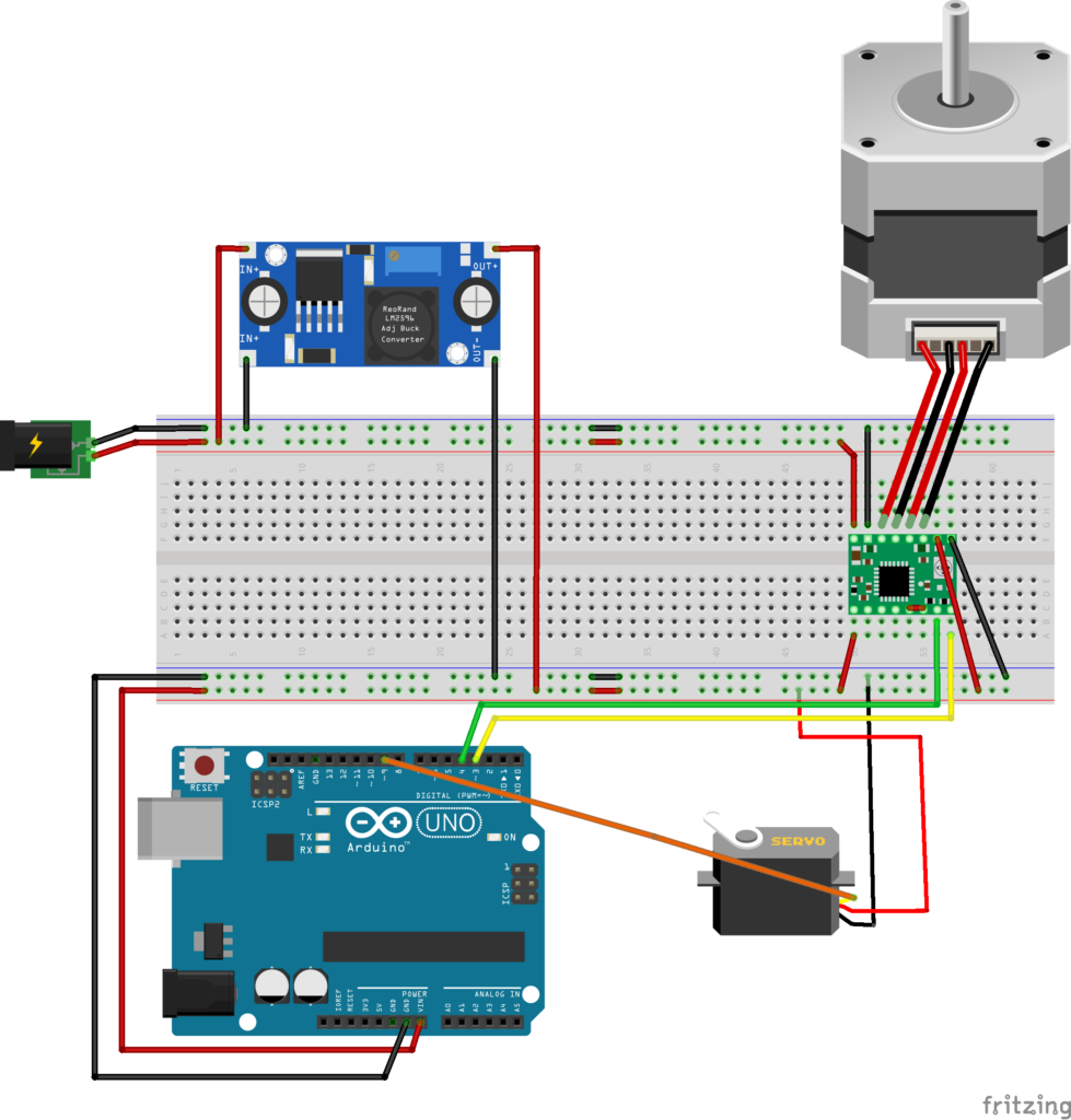
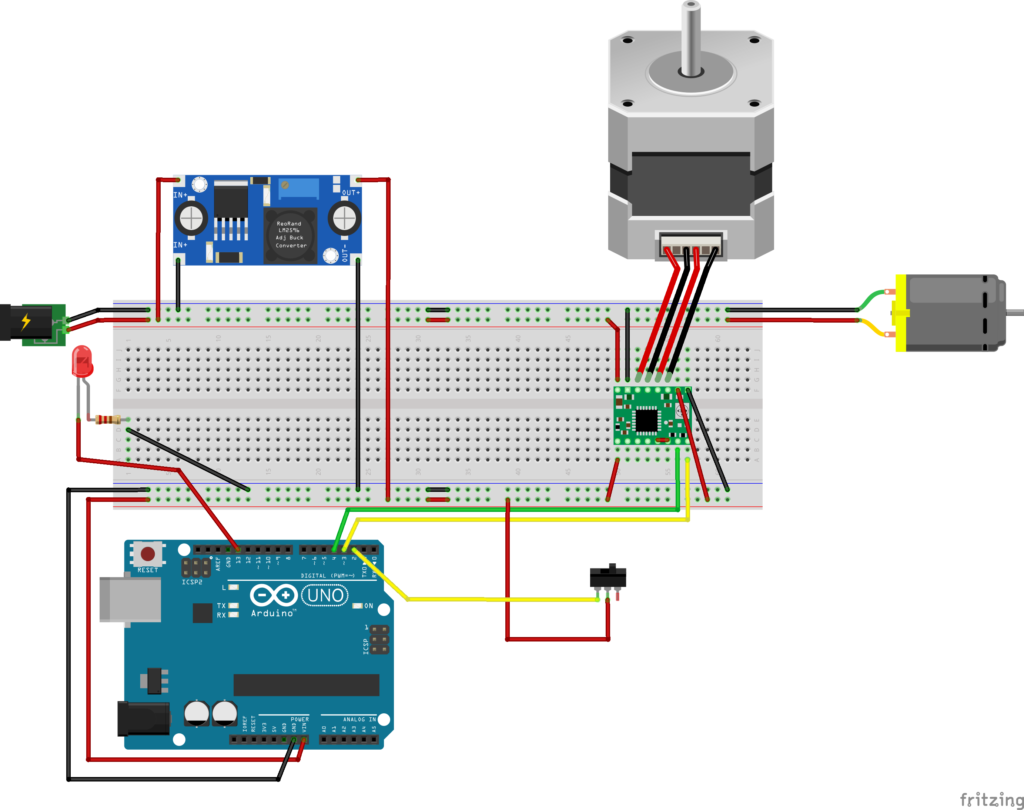
So, first of all, let’s talk about the circuit diagram. You can see the circuit diagram in the photo below. Here, I will also explain step-by-step how to make the connections.
Controlling DC motor
First, we are controlling the DC motor through a PWM regulator. So, we will connect both the positive and negative terminals of the DC motor to the output of the PWM controller or regulator. Connect the positive to positive and the negative to negative (negative is also called more appropriate ground). Similarly, we will also connect the PWM regulator to the power supply. For the input terminals of the PWM regulator, connect the positive from the power supply to the positive input and ground to ground. This way, our DC motor circuit is ready. Although I have used a separate regulator to control the DC motor, we could also have connected it to the microcontroller using a motor driver. But since I had a PWM regulator, I used it here.

Here, I am using an Arduino as the microcontroller, so we will interface the extruder kit and limit switch with the microcontroller, i.e., Arduino.
Interfacing Stepper Motor with A4988
Now, let’s talk about connecting the stepper motor to the Arduino. We always operate the stepper motor through a driver. Here, the stepper motor driver we are using is the A4988 stepper driver. The connection between the stepper motor driver and the stepper motor is given below. Additionally, the direction and pulse pins are connected to the Arduino. The direction and pulse pins can be connected to any digital pin on the Arduino, and this is where we send signals for pulses and direction. You can see in the image above how we have connected the stepper driver to the Arduino. You can do the same.

Using Limit Switch
Now it’s time to connect the limit switch to the Arduino. The limit switch has three pins, but we only use two. Which two we use depends on how we want to use the limit switch: normally open or normally closed. Here, I am using it in the normally open form, so I have connected one terminal of the limit switch to a 5V supply, and the other terminal to an interrupt pin on the Arduino.
Why to use Arduino Interrupt pin ?
By connecting the limit switch to an interrupt pin, the Arduino can immediately respond to the state change of the limit switch without continuously checking its status in the main loop (which is known as polling). This is crucial for feeding the wire( instantly to the limit switch being triggered) inside the cutter of this automatic wire cutting system.
Arduino Code for Automatic Wire Cutter
Our circuit and entire system are now ready. The next step is to upload the code to the Arduino. Before uploading, we need to create the code. The Arduino code I have created for this automatic wire cutting system is provided below. You can download it and use it in your system. An explanation of the code is also given below.
Arduino Code: Servo Motor Case
#include <Servo.h>
Servo servo1;
int servoPin = 9;
int Dir = D3;
int Pul= D4;
int arc = 15;
int pd = 100;

void setup(){
  Serial.begin(9600);
  servo1.attach(servoPin);
  pinMode(Dir, OUTPUT);
  pinMode(Pul, OUTPUT);
}

void loop(){
  float s = 6.37*arc;
  int steps = round(s);
  servo1.write(0);
  delay(1500);

  for(int i = 0; i <= steps; i++)
  {
    Serial.println(i);
    digitalWrite(Dir, HIGH);
    delayMicroseconds(pd);
    digitalWrite(Pul, HIGH);
    delayMicroseconds(pd);
    digitalWrite(Pul, LOW);
    delayMicroseconds(pd);
  }
  delay(500);
  servo1.write(180);
  delay(1500);
Explanation
int servoPin = 9;
int Dir = D3;
int Pul = D4;
int arc = 15;
int pd = 100;
These lines define several variables:
servoPinspecifies the pin number to which the servo motor is connected.Diris the direction control pin for the stepper motor.Pulis the pulse control pin for the stepper motor.arcdefines the arc or angle the servo will move.pdis the pulse delay in microseconds.
void loop() {
  float s = 6.37 * arc;
  int steps = round(s);
  servo1.write(0);
  delay(1500);

  for (int i = 0; i <= steps; i++) {
    Serial.println(i);
    digitalWrite(Dir, HIGH);
    delayMicroseconds(pd);
    digitalWrite(Pul, HIGH);
    delayMicroseconds(pd);
    digitalWrite(Pul, LOW);
    delayMicroseconds(pd);
  }
  delay(500);
  servo1.write(180);
  delay(1500);
}
float s = 6.37 * arc;calculates the number of steps needed based on thearcvalue and a constant factor (6.37).int steps = round(s);rounds the calculated steps to the nearest integer.servo1.write(0);sets the servo motor to 0 degrees.delay(1500);waits for 1.5 seconds.- The
forloop runs from0tosteps, moving the stepper motor by sending pulses:Serial.println(i);prints the current step number to the serial monitor.digitalWrite(Dir, HIGH);sets the direction pin to HIGH.delayMicroseconds(pd);waits forpdmicroseconds.digitalWrite(Pul, HIGH);sets the pulse pin to HIGH.delayMicroseconds(pd);waits forpdmicroseconds.digitalWrite(Pul, LOW);sets the pulse pin to LOW.delayMicroseconds(pd);waits forpdmicroseconds again.
delay(500);waits for 0.5 seconds.servo1.write(180);sets the servo motor to 180 degrees.delay(1500);waits for 1.5 seconds.
The loop continues to execute, moving the servo and stepper motors according to the specified sequence.
Arduino Code: DC Motor and Limit Switch
int Dir = 3;
int Pul = 4;
int arc = 5;
int pd = 100;

const byte ledPin = 13;
const byte interruptPin = 2;

void setup() {
  Serial.begin(9600);

  pinMode(ledPin, OUTPUT);
  pinMode(interruptPin, INPUT);
  attachInterrupt(digitalPinToInterrupt(interruptPin), feed, FALLING);

  pinMode(Dir, OUTPUT);
  pinMode(Pul, OUTPUT);
  // pinMode(mPin1, OUTPUT);
  // pinMode(mPin2, OUTPUT);
  // pinMode(sPin, OUTPUT);
}

void loop() {

  // analogWrite(sPin, 127);
}

void feed() {

  int val = analogRead(A0);
  arc = map(val, 0, 1023, 0, 15);

  float s = 6.37 * arc;
  int steps = round(s);
  delay(10);

  digitalWrite(ledPin, 1);
  delay(10);

  for (int i = 0; i <= steps; i++) {
    Serial.println(i);
    digitalWrite(Dir, LOW);
    delayMicroseconds(pd);
    digitalWrite(Pul, HIGH);
    delayMicroseconds(pd);
    digitalWrite(Pul, LOW);
    delayMicroseconds(pd);
  }
  delay(10);

  digitalWrite(ledPin, 0);

  delay(10);
}
Explanation
int Dir = 3;
int Pul = 4;
int arc = 5;
int pd = 100;

const byte ledPin = 13;
const byte interruptPin = 2;
Dir and Pul are the pin numbers for the direction and pulse pins of the stepper motor, respectively.
arc represents an angle value used for calculating steps.pd (pulse duration) is the delay time in microseconds between the pulses sent to the stepper motor.
mPin1, mPin2, and sPin are commented out pin numbers for additional motor or servo control, but they are not used in this code.
ledPin is the pin number for an LED (pin 13).
interruptPin is the pin number for an interrupt (pin 2).
The code sets up an interrupt-driven stepper motor control system using an Arduino. It initializes pins for direction (Dir), pulse (Pul), an LED indicator (ledPin), and an interrupt pin (interruptPin), with an attached interrupt that triggers the feed function on a falling edge. In the feed function, an analog value is read from pin A0, mapped to a range of 0-15, and used to calculate the number of steps for the stepper motor. The LED turns on, and the stepper motor is moved the calculated number of steps by toggling the direction and pulse pins with precise delays. After the movement, the LED turns off. The main loop is essentially empty, focusing on the interrupt-driven feed function for motor control.
Conclusions
This is the automatic wire cutting system, to cut the 3D printing filament into pellets. I hope, you find it interesting and useful. If you have any query or need any help, then you can comment below, we can start the discussion.
Pingback: Temperature based Fan Speed Control using Arduino - TechKnowLab
Pingback: Ender 3 Heating Failed - Reasons and Solutions - TechKnowLab
Pingback: Smart Street Light using Arduino and PIR Sensor - TechKnowLab
Hey people!!!!!
Good mood and good luck to everyone!!!!!
Pingback: How to make a WIFI controlled car using ESP8266 or Nodemcu and Blynk App - TechKnowLab
Pingback: DIY Variable Power Supply made using 3D Printing for Lab Bench - TechKnowLab
Pingback: Control Stepper Motor with Raspberry pi - steppermotor.net